39 B58FZS 0000000078 EN 002
FUNCTIONS
Skid-steer change frame
⚠ WARNING
Risk of injury due to implements falling down!
The implement may fall down if the implement locking mechanism is open or not locked correctly. This
can cause serious injury to persons standing in the surrounding area.
Only actuate the implement locking mechanism when the implement is set down on the ground or
on a secure rack.
Always check that the implement is correctly locked.
⚠ CAUTION
Risk of crushing due to spring tension!
There is spring tension on the handle of the implement locking mechanism, which closes the locking
mechanism when the handle is lifted. Improper use can lead to injury to hands and fingers.
Always operate the handle with one hand and grab it in the middle.
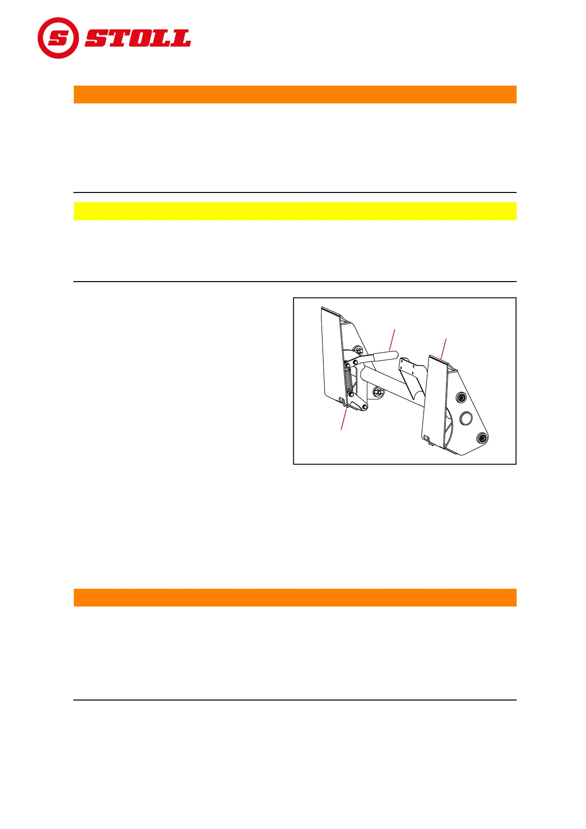
The mechanical implement locking mechanism
on skid-steer change frames is actuated
manually.
To attach implements, the edge of the mounting
surfaces is pushed into the mounting on the
implement. As soon as the implement is resting
on the change frame, the locking mechanism is
closed with the lever. The locking hooks then
engage with the lug on the implement.
4.1.2 Hydraulic implement locking mechanism – Hydro-Lock
⚠ WARNING
Risk of injury due to implements falling down!
If not installed or operated correctly, the implement can fall down. This can cause serious injury to
persons standing in the surrounding area.
The hydraulic implement locking mechanism must only be installed by a specialist workshop.
Only use switches that are approved by STOLL.
Set the implement on the ground or on a safe support before using the implement locking function.
As an option, the front loader can be equipped with a hydraulic implement locking mechanism.
It attaches the implement to the change frame via 2 pins activated by a hydraulic cylinder.
Fig. 22 Mechanical implement locking mechanism on
skid-steer change frames
Legend
1Lever
2 Mounting surface
3 Locking hooks
33
2
2
1
1
B06M