TIMING BELT ASSEMBLY
MECHANICAL
B: INSTALLATION
ER ASSEMBLY AND BELT IDLER
1)
Preparation for installation
of
automatic belt ten-
sion adjuster assembly:
CAUTION:
Always use a vertical type pressing tool to
move the adjuster rod down.
Do
not use a lateral type vise.
Push the adjuster rod vertically.
Be sure to slowly move the adjuster rod down
applying a pressure of
294
N
(30 kgf,
66
Ib).
Press-in the push adjuster rod gradually tak-
ing more than three minutes.
Do
not allow press pressure to exceed
9,807
N
(1,000
kgf,
2,205
Ib).
Press the adjuster rod as far as the end sur-
face of the cylinder. Do not press the adjuster
rod into the cylinder. Doing
so
may damage the
cylinder.
Do
not release the press pressure until stop-
per pin is completely inserted.
(1)
Attach the automatic belt tension adjuster
assembly to the vertical pressing tool.
(2)
Slowly move the adjuster rod down with a
pressure
of
294
N
(30
kgf,
66
Ib) until the adjust-
er rod is aligned with the stopper pin hole in the
cy1 inde r.
1.
AUTOMATIC BELT TENSION ADJUST-
\I
1
H2M23821
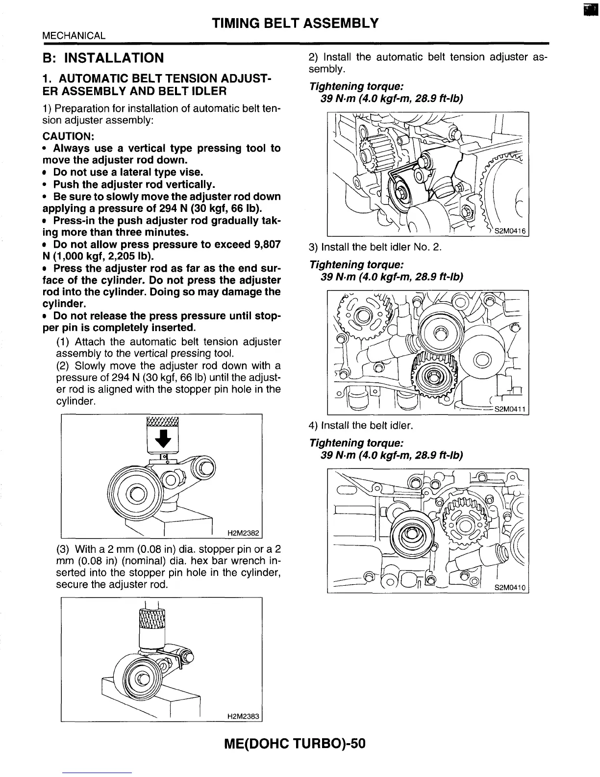
(3)
With a
2
mm
(0.08
in) dia. stopper pin or a
2
mm
(0.08
in) (nominal) dia. hex bar wrench in-
serted into the stopper pin hole in the cylinder,
secure the adjuster rod.
2)
Install the automatic belt tension adjuster as-
sembly.
Tightening torque:
39 N-m
(4.0
kgf-m,
28.9
ft-lb)
3)
Install the belt idler No.
2.
Tightening torque:
39 N.m
(4.0
kgf-m, 28.9 ff-lb)
4)
Install the belt idler.
Tightening torque:
39 N.m
(4.0
kgf-m, 28.9 ft-lb)
ME(D0HC TURBO)-50