2-10 PERIODIC MAINTENANCE
Adjustment
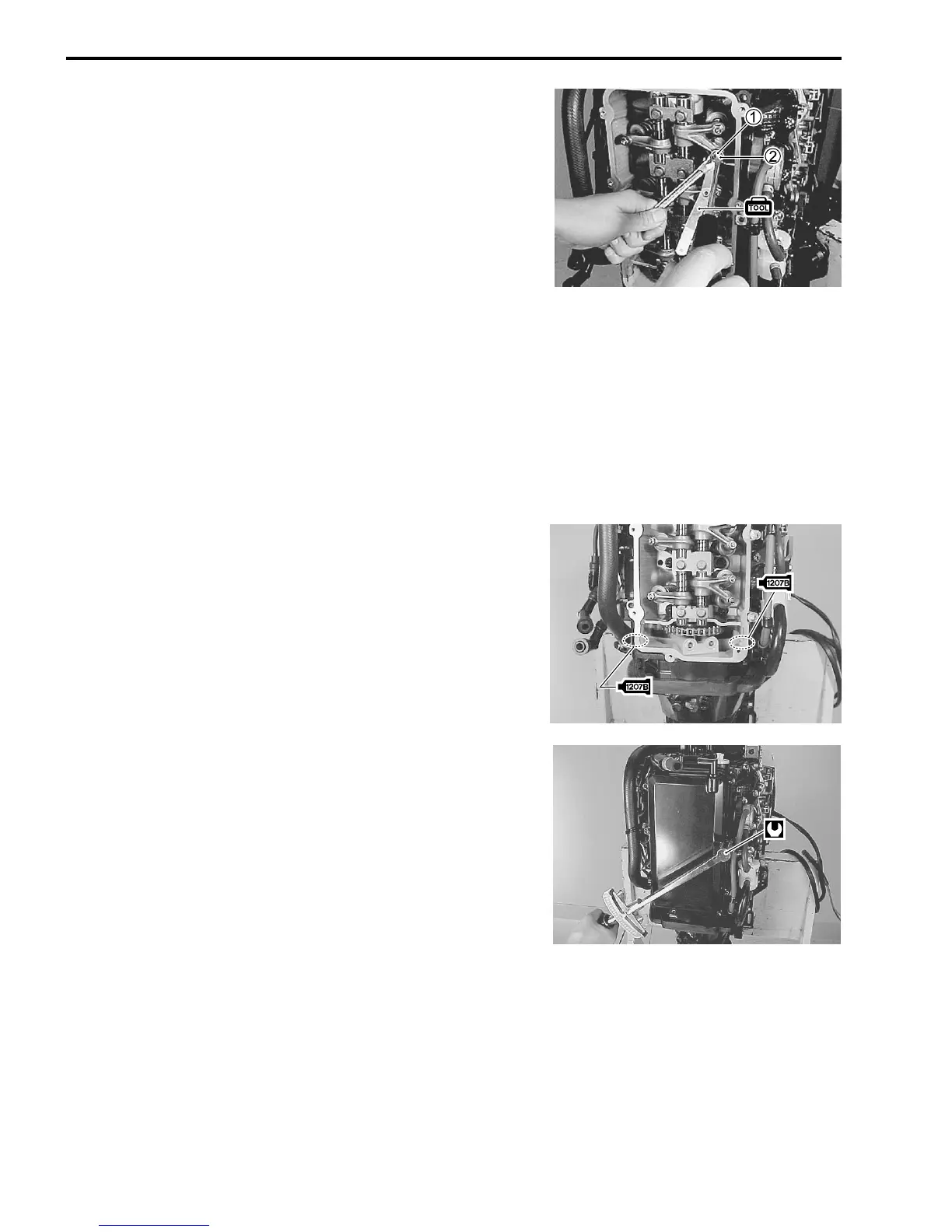
(6) Loosen valve adjusting lock nut 1.
(7) Turn valve adjusting screw 2 to bring valve clearance to
within the specification.
[ 09900-20803 : Thickness gauge
(8) Tighten valve adjusting lock nut 1 to specified torque while
holding valve adjusting screw 2.
! Valve adjusting lock nut :
11 N
.
m (1.1 kg-m, 8.0 lb.-ft.)
(9) Recheck valve clearance.
Reassembly
After checking and adjusting all valves, reverse removal proce-
dure for installation.
• Install the cylinder head cover. (See page 7-9)
NOTE :
Examine cylinder head cover gasket for damage. Always re-
place gasket if sealing performance is suspect.
• Tighten cylinder head cover bolts to specification.
! Cylinder head cover bolt :
11 N
.
m (1.1 kg-m, 8.0 lb.-ft.)