4-10 ELECTRICAL
INSPECTION
IGNITION SWITCH (Remote control model)
[ 09930-99320 : Digital tester
SS
SS
S Tester range : (Continuity)
1. Disconnect the ignition switch from remo-con box wiring har-
ness.
2. Check continuity between wiring leads at the key positions
shown in the chart.
If out of specification, replace ignition switch.
Key
Position
11
11
1 OFF
Switch Lead Wires
Black
Green White Gray Brown
Orange
22
22
2 ON
33
33
3 START
44
44
4 FREE
55
55
5 PUSH
: Continuity
Black
Green
White
Gray
Orange
Brown
1 (OFF)
2 (ON)
3 (START)
4 (FREE)
5 (PUSH)
PUSH
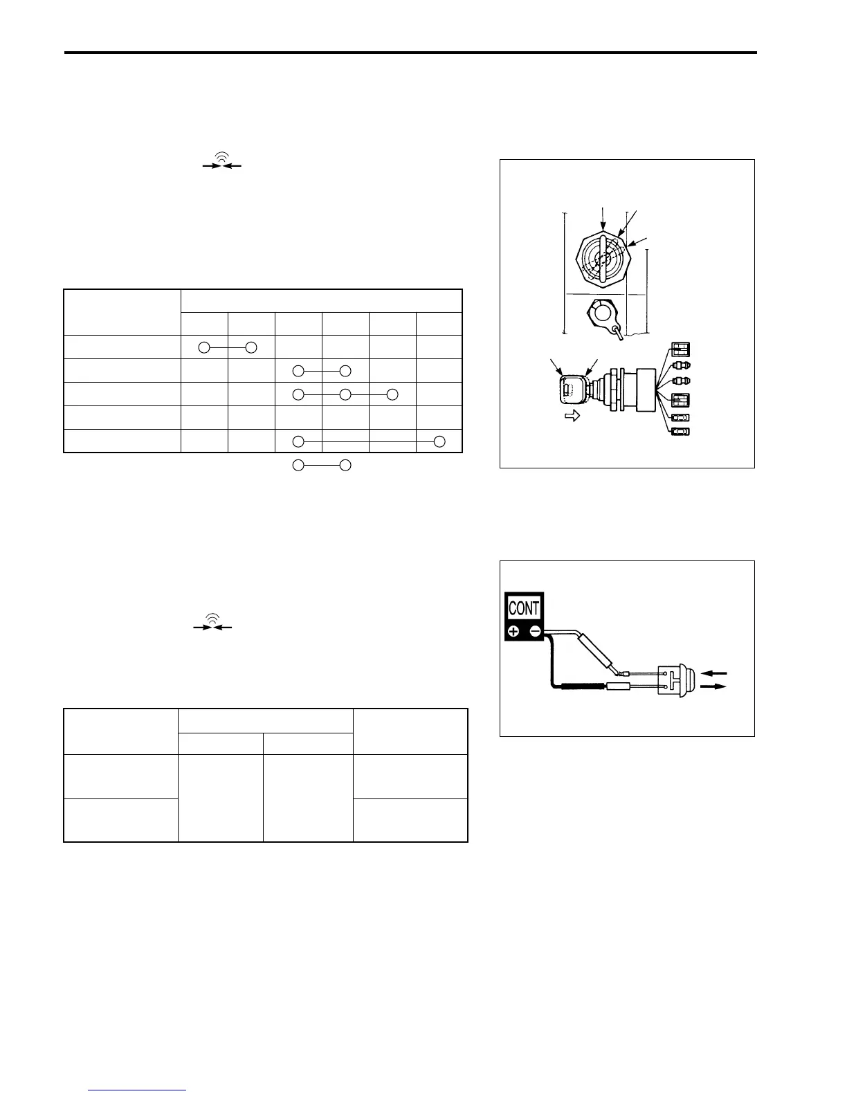
STARTER SWITCH ( Tiller handle model )
[
09930-99320 : Digital tester
S Tester range : ( Continuity )
1. Disconnect the starter switch lead wire.
2. Check continuity between the wiring leads under the condi-
tion shown below.
Tester probe connection
Tester indicates
Red
++
++
+ Black
--
--
-
Starter button
Infinity
not depressed
White/Red Brown
Starter button
Continuity
depressed
W/R
Br
Depressed
Not depressed