ELECTRICAL 4-9
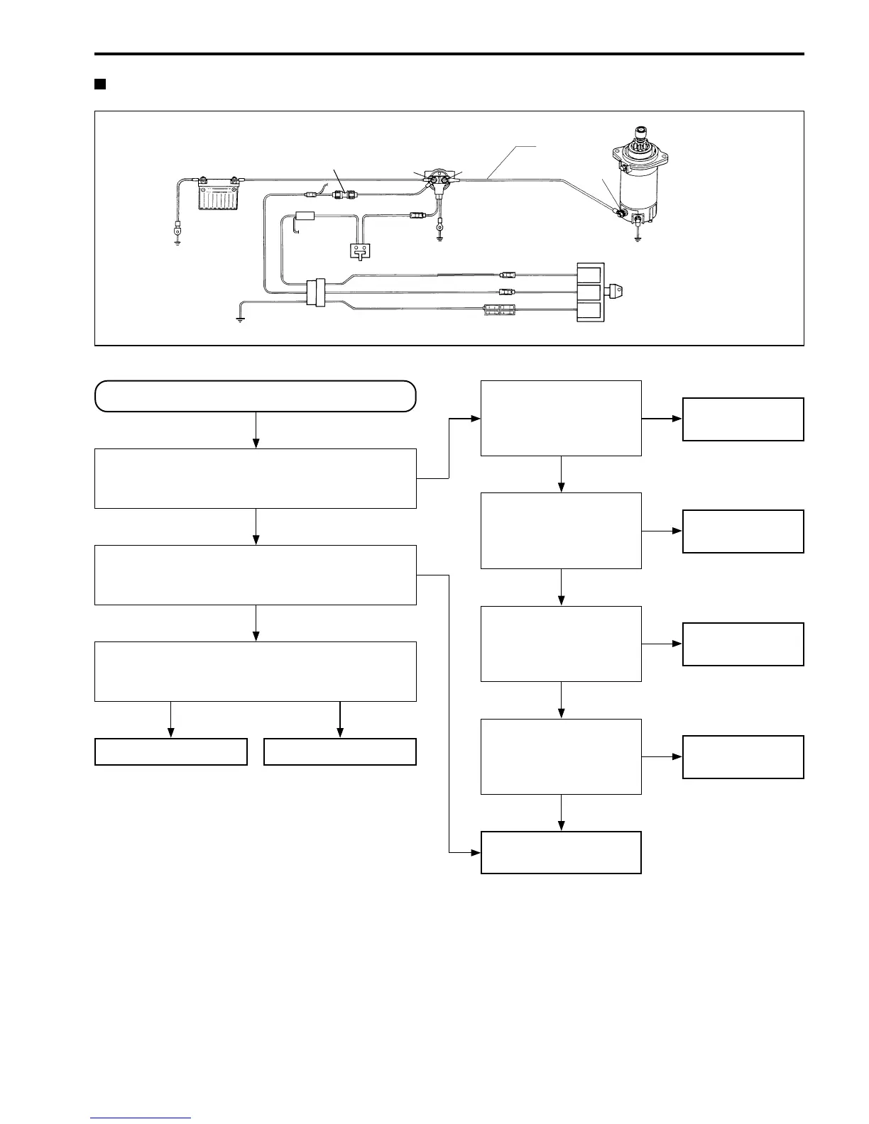
Remote control models
Circuit check schematic
Check starter motor.
(See page 4-16.)
Sub cable
1
+
-
3
Starter motor
GND
Ignition switch
ST
BAT
GND
GND
Neutral
switch
GND
GND
Battery
Starter motor relay
2
Starter motor will not run.
Check for relay “click” sound when turning
ignition switch to “START”.
Is there “click” sound?
Measure voltage at terminal 2 with ignition
switch at “START”. It must be above 12 V.
Is result OK?
Measure voltage at terminal 3 with ignition
switch at “START”. It must be above 12 V.
Is result OK?
Starter motor failure Sub cable failure
Measure voltage at
terminal 1. It must
be above 12V.
Is result OK?
Check 25A fuse and
fuse case.
(See page 4-4.)
Is result OK?
Check ignition switch
function.
(See page 4-10.)
Is result OK?
Check function of
neutral switch.
(See page 4-11.)
Is result OK?
Check starter motor
relay.
(See page 4-12.)
Starter motor relay
failure
Battery cable
failure
25A fuse or
fuse case failure
Ignition switch
failure
Neutral switch
failure
YES
YES
YES
NO
YES
YES
YES
NO
NO
NO
NO
NO
NO
W
Y/G
W/R
Br
B
B
Br
Br
W/R
Fuse
W/R
YES