POWER UNIT 6-11
4. Apply the seal to the bolts and the nuts.
' 99000-31120: Suzuki Silicone Seal
5. Tighten the ten bolts and the two nuts.
# Power unit mounting bolt / nut:
8 mm 23 N
.
m (2.3 kg-m, 16.5 lb-ft)
10 mm 50 N
.
m (5.0 kg-m, 36.0 lb-ft)
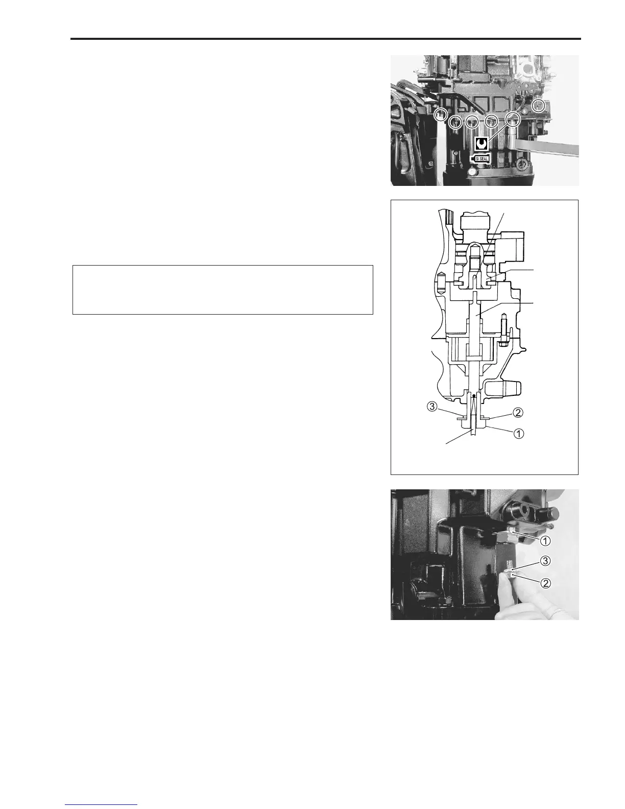
OIL PUMP SHAFT ENGAGEMENT
1. Screw (2 – 3 turns) the oil pump stopper 1 with the lock
washer 2 and the gasket 3 onto the oil pan.
!
Do not screw the oil pump shaft stopper fully before
engaging the oil pump shaft with the groove in the cam-
shaft.
2. Engage the oil pump shaft with the groove in the camshaft
by using a screw driver as shown.
While holding the screw driver, tighten the oil pump stopper
1.
# Oil pump stopper: 50 N
.
m (5.0 kg-m, 36.0 lb-ft)
3. Bent two locking edges of the lock washer 1 toward the
opposite direction each other. (upward and downward)
4. Tighten the plug 2 with the gasket 3.
# Oil pump stopper plug: 23 N
.
m (2.3 kg-m, 16.5 lb-ft)
EXHAUST MANIFOLD
Install the exhaust manifold.
# Exhaust manifold bolt / nut: 23 N
.
m
(2.3 kg-m, 16.5 lb-ft)
Groove
Camshaft
Oil pump
shaft
Screw driver
 Loading...


