137
Water Reservoir Tank
A “see through” plastic reservoir tank is connected to the
radiator by a hose. As the vehicle is driven, the coolant
is heated and expands. The portion of the coolant dis-
placed by this expansion flows from the radiator into the
reservoir tank. When the vehicle is stopped and the cool-
ant cools and contracts, the displaced coolant is drawn
back into the radiator by vacuum.
Thus, the radiator is kept filled with coolant to desired
level at all times, resulting in increasing cool efficiency.
Coolant level should be between “FULL” and “LOW”
marks on the reservoir tank.
Coolant should be added only to the reservoir tank as
necessary.
Water Pump
The centrifugal type water pump is used in the cooling
system. The pump impeller is supported by a totally
sealed bearing. The water pump can not be disas-
sembled.
Thermostat
A wax pellet type thermostat is used in the coolant outlet
passage to control the flow of engine coolant, to provide
fast engine warm up and to regulate coolant tempera-
tures.
A wax pellet element is hermetically contained in a metal
case, and expands when heated and contracts when
cooled.
When the pellet is heated and expands, the metal case
pushes down the valve to open it.
As the pellet is cooled, the contraction allows a spring to
close the valve.
Thus, the valve remains closed while the coolant is cold,
preventing circulation of coolant through the radiator.
At this point, coolant is allowed to circulate only through-
out the engine to warm is quickly and evenly.
As the engine warms, the pellet expands and the thermo-
stat valve opens, permitting coolant to flow through the
radiator.
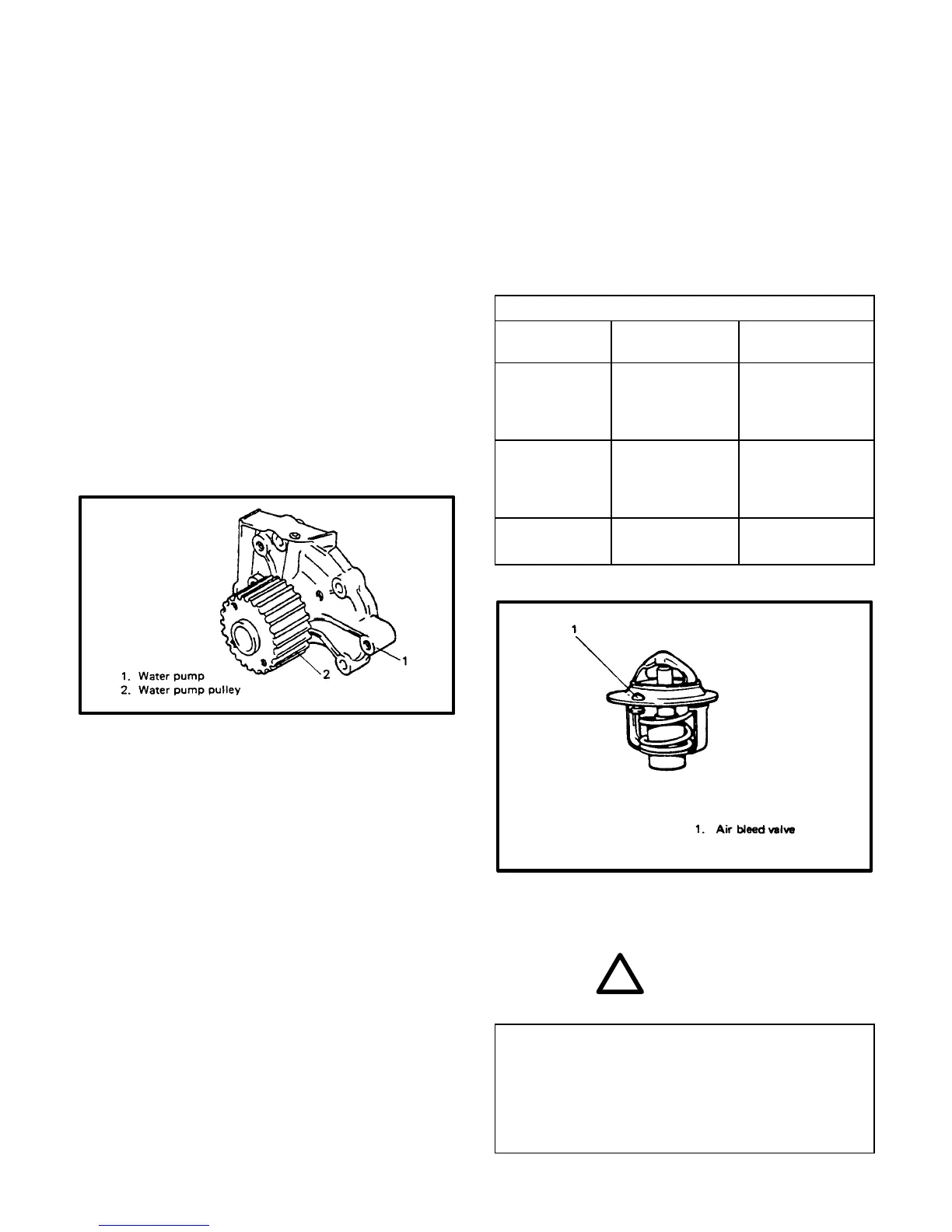
In the top portion of the thermostat, and air bleed valve
is provided; this valve is for venting out the gas or air, if
any, that is accumulated in the circuit.
There are two types of thermostats, A and B, as given
below. Either one is used depending on vehicle specifi-
cations. The temperature at which the valve begins to
open is stamped of each thermostat. Be sure to note this
stamped temperature for replacement.
Thermostat Functional Specifications
Thermostat
“A”
Thermostat “B”
Temp. at
which valve
begins to
open
82° C (179° F) 88° C (190° F)
Temp. at
which valve
becomes
fully open
95° C (203° F) 100° C (212° F)
Valve Lift More than
8 mm at 95° C
More than
8 mm at 100° C
COMPONENT REMOVAL
WARNING
!
Check to make sure that cooling water
temperature is cold before removing any
cooling system components.
Make sure to disconnect the negative
battery cable from the negative terminal
of the battery before removing any parts.