111
ISC STEPPER MOTOR CONTROL
The ISC stepper motor is controlled in the following modes according to various conditions.
Operation shutdown: When the battery voltage is less than 9.0 V, operation of the ISC is halted.
Initialization: When the ignition key is switched from ON to OFF, initializing is performed, and ISC is placed in
standby imposition of step 80.
Stop mode: When the engine speed is 50 rpm or less, fixed at step 80.
Start mode: When engine is at low rpm (cranking), fixed at bypass air amount when starting.
Normal mode: Normally, bypass air amount is determined by adding the following correction to the basic bypass
air amount which changes according to the cooling water temperature.
Correction immediately after starting: The bypass air amount is determined according to the cooling water
temperature after starting, and a correction amount is gradually decreased according to the engine warm–up
status.
RPM feedback correction: The bypass air amount is corrected according to the difference between the present idle
rpm and the target idle rpm.
Electrical load idle–up correction: When the headlights are on, the bypass air amount is increased by a specified
amount.
Dash pot correction: When the idle switch is ON and the engine rpm has changed from a high region to a certain
level or below, the bypass air amount is increased, and the emission of HC is prevented.
Atmospheric pressure correction: The bypass air amount is corrected according to the atmospheric pressure.
Radiator fan idle–up correction: When the radiator fan is operating, the bypass air amount is increased by a
specified amount.
D range idle–up correction: The bypass air amount is increased by a specified amount according to the shift lever
operating status (R, D, 2, L).
Correction when load changes: When shifting to no–correction status in the idle–up status described above, the
correction amount is gradually decreased.
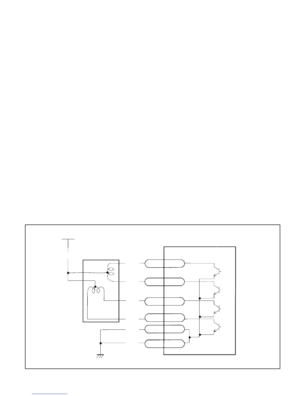
+12V
(VIA IG SW)
B/R
ISC VALVE
R/B
R
R/Y
R/BL
B/BL
B
COLOR CODE
R – RED
B – BLACK
Y – YELLOW
BL – BLUE
ECM
11
SMA
12
SMB
SMC
SMD
13
14
9
17
E01
E1