64
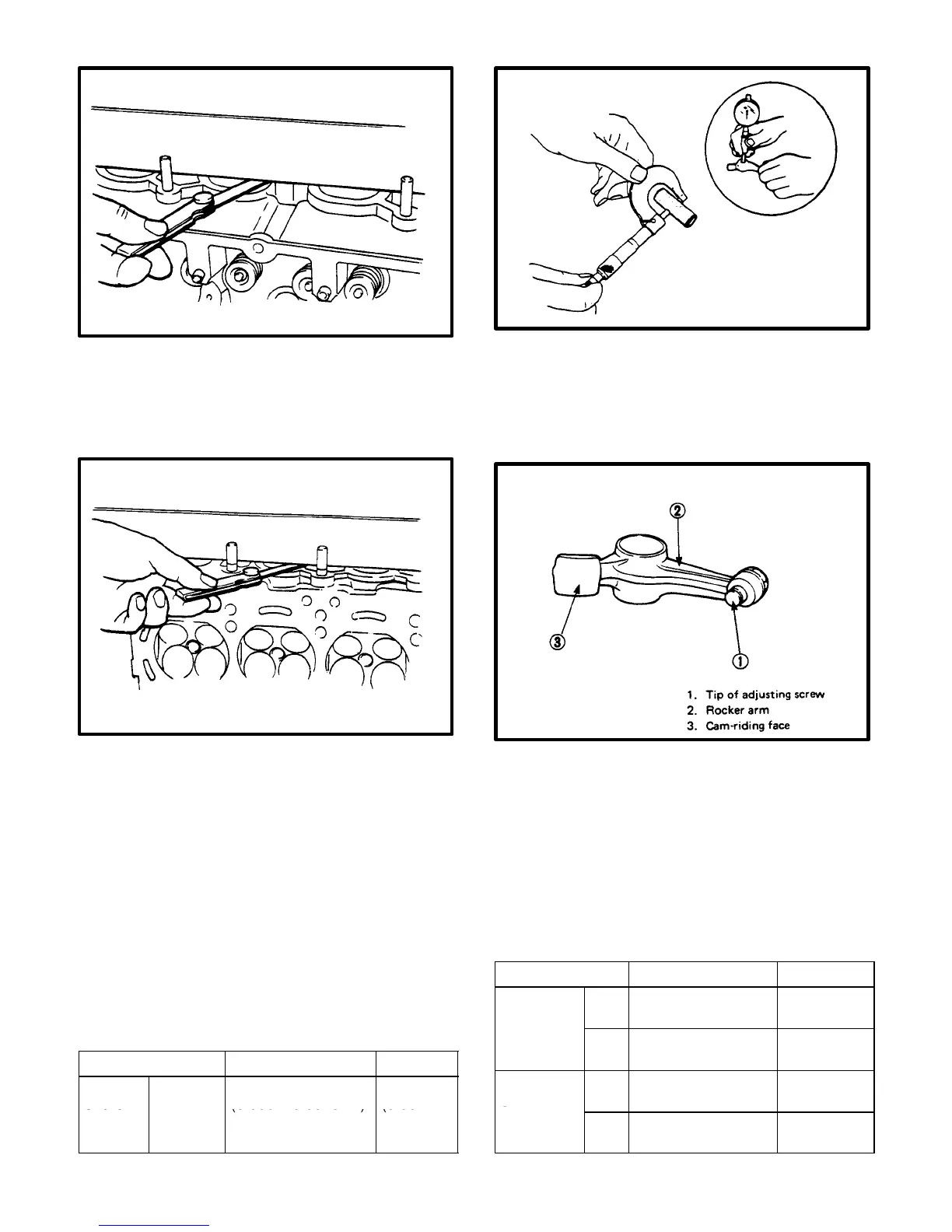
Measuring Surface of Intake Manifold Seating Face
Measuring surface of Exhaust Manifold Seating Face
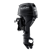
Rocker–Arm Shaft and Rocker Arms
Shaft–to–arm clearance (IN & EX): Using a
micrometer and a bore gauge, measure rocker
shaft dia. and rocker arm I.D..
The difference between two readings is the arm–
to–shaft clearance on which limit is specified. if
the limit is exceeded, replace shaft or arm, or
both.
Item Standard Limit
Arm–to
shaft
Intake &
0.005 – 0.040 mm
(0.0002–0.0016 in.)
0.06 mm
(0.0024
clear-
ance
Exhaust
in.)
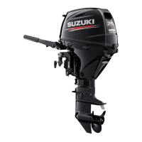
Wear of rocker–arm and adjusting screw: If the
tip (1) of adjusting screw is badly worn, replace
screw. Arm; must be replaced if its cam–riding
face (3) is badly worn.
Visually examine each rocker–arm wave washer
for evidence of breakage or weakening. Be sure
to replace washers found in bad condition.
Valve Guides
Using a micrometer and bore gauge, take diameter read-
ings on valve stems and guides to determine stem clear-
ance in guide. Be sure to take a reading at more than one
place along the length of each stem and guide.
Item Standard Limit
Valve
stem
Int 4.965–4.980 mm
(0.1955–0.1960 in.)
–––––––––
diameter
Exh 4.950–4.965 mm
(0.1949–0.1954 in.)
–––––––––
Valve
guide I.D.
Int 5.000–5.012 mm
(0.1969–0.1973 in.)
–––––––––
Exh 5.000–5.012 mm
(0.1969–0.1973 in.)
–––––––––