114
CODE RETRIEVAL PROCEDURE
NOTE:
• When there are multiple failure locations, all of the codes are displayed 3 times each in order of priority of code.
• See Section 2B for AT system diagnosis codes.
NOTE:
The jumper will perform diagnostic checks on various electrical components.
3. Place the gear selector into park, apply the park brake and turn the ignition switch to the off position.
4. Open the right lid in the storage compartment located behind the cab. Locate the plug-in connector coming from
the small section of wire-harness.
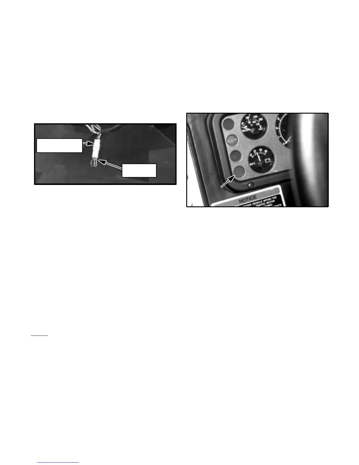
5. Plug the diagnostic jumper into the plug-in connector with the blue/white wire and the black wire.
DIAGNOSTIC
JUMPER
CONNECTOR ON
MAIN HARNESS
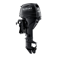
6. Turn the ignition switch to the on position and note the brake fluid level warning light at the lower left corner of the
instrument panel.
7. The light will flash a code to let you know that everything is normal (Code 12) or to let you know which specific
component needs attention.
8. The light will first flash to correspond to the first digit of the code, then flash again to correspond with the second
digit of the code.
9. A Code 14 would turn the light on for 0.3 seconds then off for one second (long pause), then on-off, on-off, on-off,
on-off (the last four flashes will be short quick flashes).
10. If a Code 43 were present the light would - flash then pause,... flash then pause,... flash then pause,... flash then
pause,
then
flash, flash, flash (four long pauses followed by three quick flashes).
11. The code will continue to repeat itself until the ignition switch is turned off.
NOTE:
If there are multiple faults, each code will be displayed three (3) times starting with the lowest numbered code.
12. Turn the ignition key to the off position, then back to the on position each time you want to take a reading.
The following list shows which code number corresponds to which component and lists possible causes for each fault:
CODE
11 Pressure Sensor – Voltage at pin 25 (green/yellow wire) of the 34 pin ECU connector is either higher than 4.5
V or lower than 0.19V. Failsafe Mode: Fixed to specified pressure valve
12 Normal – System operating normally
13 Throttle Sensor – Voltage at pin 33 (gray/yellow wire) of the 34 pin ECU connector is either higher than 4.73V
or lower than 0.25V.
14 O2 Sensor – No signal for a length of time at pin 24 of the 34 pin ECU connector.
15 Crank Angle Sensor – While in starting mode, no signal is seen at pin 16 (brown/red wire) of the 34 pin ECU
connector.