197
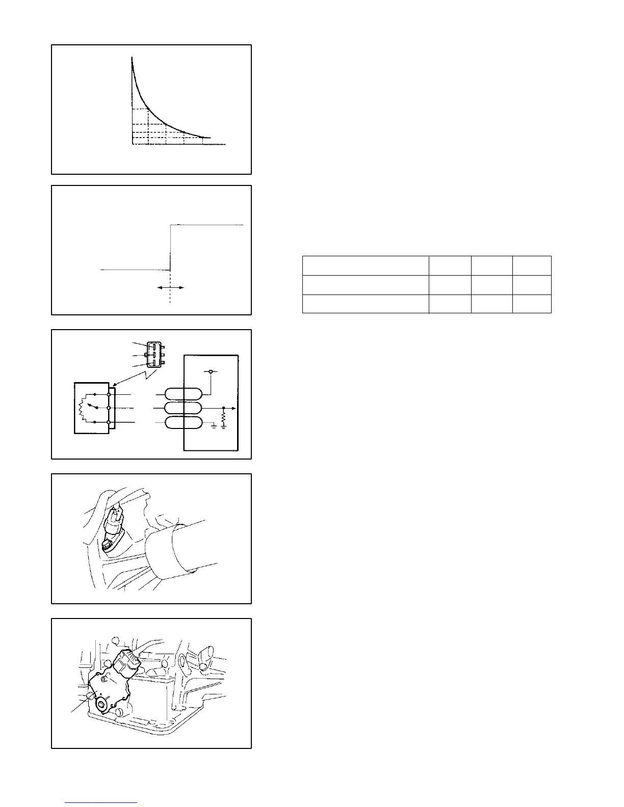
THERMISTOR
(BETWEEN THW
AND E2
TERMINALS)
RESISTANCE
kΩ
(5.74)
2.28∼2.61
(1.15)
(0.584)
0.303~0.326
0
20 40 60 80
(°C)
TEMPERATURE
EACH SHIFT SOLENOID
TERMINAL PRESSURE
HI (BATTERY VOLTAGE)
LO (ABOUT 0V)
SOLENOID OFF
SOLENOID ON
VCC
VTA
E2
THROTTLE SENSOR
ECM
5V
LTG/R
GY/Y
BL/Y
26 VCC
VTA
33
34
E2
1
1. SHIFT SWITCH
COLOR CODE
LTG – LIGHT GREEN
R – RED
GY – GRAY
Y – YELLOW
BL – BLUE
WATER TEMPERATURE SIGNAL
Changes in the resistance of the water temperature sen-
sor are read as changes in voltage, and are input as the
cooling water temperature.
The gearshift point changes according to the tempera-
ture.
OUTPUT SIGNALS
Shift solenoid No. 1 (direct clutch solenoid) and No. 2
(2
nd
brake solenoid) signals
These are signals which, based on the input signals,
operate the shift solenoids No. 1 and No. 2.
1
st
2
nd
3
rd
Shift
Solenoid
No.
1
Shift
Solenoid
No.
2
ON
OFF
ON
ON ON
OFF
VEHICLE SPEED SENSOR
In the AT case, and picks up the signal rotor number of
the output shaft by sensor.
SHIFT SWITCH
Installed on the manual shift shaft, and by applying bat-
tery voltage to the controller according to the position of
the selector lever, detects the present positions of the
selector lever and manual valve.
SENSOR SWITCHES
Throttle sensor
Installed on the throttle shaft, detects throttle opening.
See section 1C for details.