162
SYSTEM OPERATION
Trombetta’s P613–K1 throttle control solenoid kit con-
sists of a “three wire,” dual coil solenoid, electromechani-
cal control module and stainless steel sheathed pull
cable. The sheathed pull cable allows the solenoid to be
mounted away from hostile environments, such as
engine vibration and high temperature.
The throttle solenoid is activated automatically for “on
demand” to bring the idle speed to a pre–set position.
The control module allows the solenoid to operate as a
continuous duty device. When the module is wired as
recommended, applying 12 VDC to the white/black wire
applies voltage to the hold–in and pull–in coil of the sole-
noid. After 0.5 seconds to 0.75 seconds, power is auto-
matically removed from the pull–in coil. Power will
remain at the hold–in coil until the 12 VDC signal is
removed from the white/black wire.
TROUBLESHOOTING HINTS
If the solenoid will not engage, check the following:
1. Check the stranded pull cable for damage (e.g.,
melted or crimped sheath).
2. Check the stranded pull cable for binding.
3. Check system voltage at the green/yellow and white/
black wires.
4. Check module terminals for proper voltage and
operation. If the module does not meet these specifi-
cations, replace it.
5. Check solenoid resistance (remove wires from mod-
ule). If resistance is not within specifications listed
below, replace the solenoid.
12VDC System
0.17 ohms
White to Black wire
0.13 ohms
Red to Black wire
6. Be sure cable is not bent beyond guidelines.
7. Check for proper adjustments.
8. Contact the factory if you are unable to resolve the
problem.
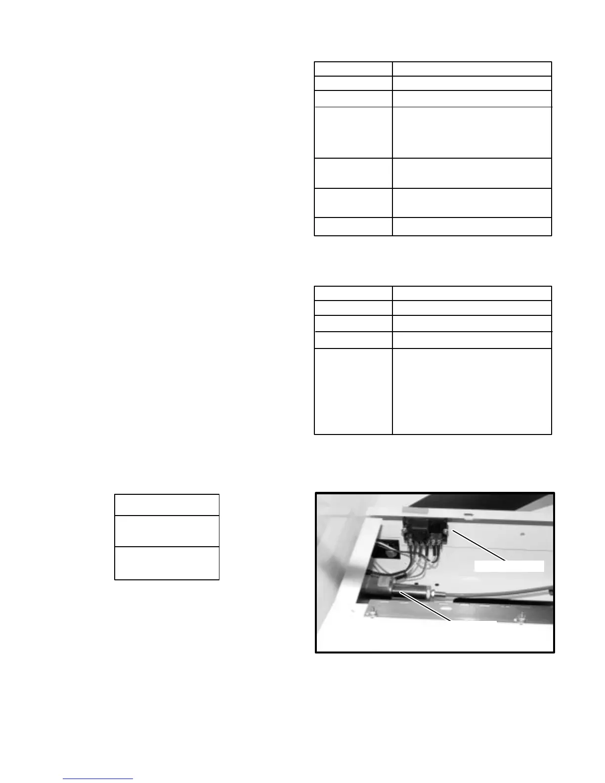
Wire Color
CONTROL MODULE VOLTAGE MEASUREMENTS
Voltage
Black Chassis Ground
Green/Yellow 12 VDC when key ON
White/Black 12 VDC when vehicle speed
is below 41 MPH ± 3MPH
(33 MPH ± 3 MPH for
53749 NYC Mod.)
Red 12 VDC when 12 VDC is
present at white/black wire
White 12 VDC for 0.5 to 0.75 seconds
after 12 VDC at white/black wire
Black Common for solenoid
Wire Color
SPEED LIMIT MODULE
Voltage
Black Chassis Ground
White/Green 12 VDC when key ON
White/Black Output to Control Module
Orange/Green Input from Speed Sensor
(Same signal that oper-
ates the speedometer on
the instrument panel. So
if the speedometer is
working, this signal is
working as well.)
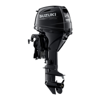
SOLENOID
SPEED LIMITER