196
AT CONTROLLER
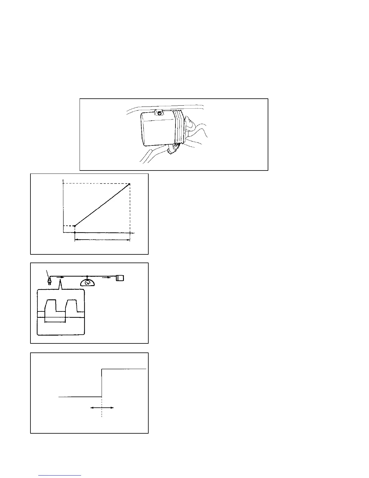
The controller is installed behind the engine compartment under the storage compart-
ment center section, and is integrated with the EPI controller. The output signals of the
shift solenoids No. 1, No. 2, and No. 3 are transmitted according to the input signals from
each sensor and perform shifting between 1
st
gear, 2
nd
gear, and 3
rd
gear.
A diagnosis function is provided for detecting abnormalities in the controller unit and
input and output signals. When a system error occurs, a failsafe function operates, allow-
ing the minimal driving performance to be maintained.
VTA
OUTPUT
TERMINAL
VOLTAGE
(V)
4.1
0.8
FULLY
CLOSED
THROTTLE LEVEL ROTATION ANGLE
FULLY
OPENED
VEHICLE SPEED SENSOR
CONTROLLER
PERIOD BETWEEN
PULSES
HI (BATTERY VOLTAGE)
LO (ABOUT 0V)
WHEN NOT SELECTED WHEN SELECTED
INPUT SIGNAL
Throttle signal
Voltage changes in the throttle sensor are read as sig-
nals, and input as the throttle opening.
These are used as a reference for changing gears
together with the vehicle speed signal.
SHIFT POSITION SIGNAL
According to output for the shift lever switch, the pres-
ent selector lever position and manual valve position
are detected.
These are used as a reference for determining the driv-
ing gear for a vehicle speed.
VEHICLE SPEED SIGNAL
Changes in the rpm of the output pulse of the vehicle
speed sensor are read as vehicle speed signal and are
input as vehicle speed.
These are used as a reference for changing gears
together with the throttle signal.