173
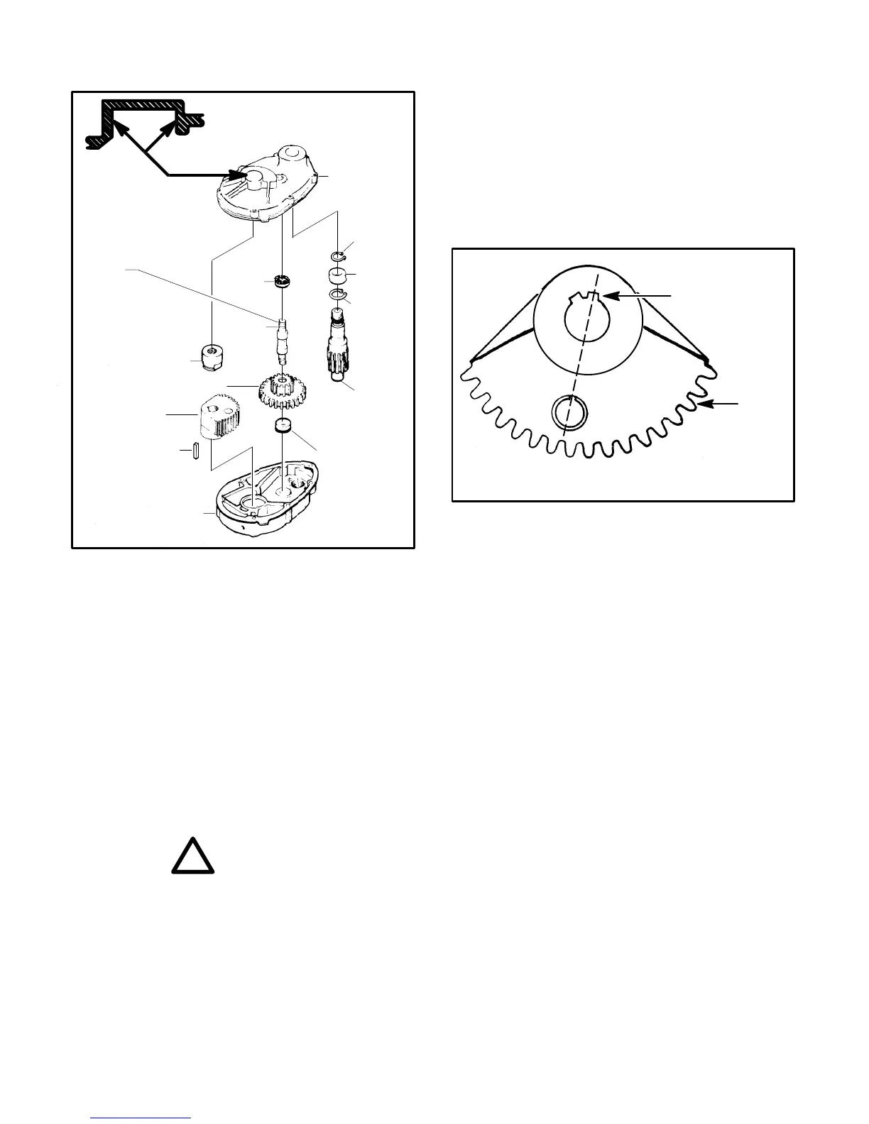
STEERING GEAR
Driven
Steering Gear
INSIDE SURFACE
MACHINED TO
PROVIDE CLEARANCE
FOR NUT
IDLER
BOLT
WITHOUT
LUBRICATION
FITTING
Key
Upper
housing
Lower housing
FIGURE 15
Pinion
Gear
Shaft
Washer
Cluster Gear
Nut
Washer
Retaining
Ring
Ball
Bearing
Bolt
Retaining
Ring
Disassembly
With the horn wire disconnected, remove the horn button
and lift wire from the pinion shaft.
Remove the steering wheel retaining nut and lift the
wheel from the shaft.
Remove the top idler bolt nut and washer and the gear
case retaining screws. The case may now be lifted off.
Remove the driven gear nut. The gear may now be
removed by the use of a 1/2–20 knock–off (obtainable
through your Cushman dealer).
Remove the lower idler bolt nut and washer and lift the
cluster gear and idler bolt from the lower case.
!
CAUTION
• Inspect all gears and splines for wear or dam-
age. If the wear or damage is excessive, replace
with new parts. Also inspect the pinion shaft for
wear.
Reassembly
Place a locating washer, with the knurled side down, over
the hole for the idler adjustment bolt. Insert the adjust-
ment bolt, add another locating washer on the outside of
the lower housing with the knurled side against the hous-
ing. Secure with a nut and tighten finger tight. See Figure
15.
Place a liberal amount of lubrication in recess of idler
adjusting bolt and place the cluster gear over the idler
adjusting bolt.
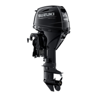
Determine the correct keyway in the driven gear (see
Figure 16 below) and install gear. Torque the steering
bushing nut to 40–50 ft.–lbs. (54 –70 N⋅m). Apply a liberal
amount of lithium based lubricant to the gear teeth and
all bearing surfaces.
Ref.
Driven
Gear
Part
No.
830167
Use this keyway
(Viewed from top of gear)
FIGURE 16
Adjust the height of the lower housing as shown in Figure
17 (page 22). Tighten the support mounting screws.
Tighten the five lower housing and support bracket
screws to 20–25 ft.–lbs. (27–34 N⋅m).
Place one locating washer, knurled side up, over the idler
adjustment bolt. Assemble upper housing to lower hous-
ing. Place another locating washer over the adjustment
bolt with the knurled side against the upper housing.
Secure with a nut and tighten finger tight. Tighten hous-
ing attaching screws to 8–10 ft.–lbs. (11–14 N⋅m).
Backlash Adjustment
The weight of the vehicle must be on the wheels or hold
the front wheel to prevent the fork from turning. Loosen
the upper and lower idler bolt adjusting nuts, turn the
steering wheel counterclockwise and hold with light pres-
sure. Snug the lower idler adjusting nut and then the
upper adjusting nut. Use a socket wrench and at least a
4” (101.6 mm) extension. Care MUST be exercised to
avoid cocking the idler bolt. With slight pressure on the
steering wheel in counterclockwise direction, tighten
lower nut 40–50 ft.–lbs. (54–70 N⋅m). Check backlash for
a maximum of 1/4” (6.4 mm) travel of the steering wheel
rim, then tighten upper adjusting nut 40–50 ft.–lbs.
(54–70 N⋅m). Check operation of the steering for free
operation. A slight amount of roughness is permitted
after the front fork and wheel has been rotated either