Chapter 6 Maintaining and Troubleshooting the TimeProvider
Diagnosing the TPIU
154 TimeProvider User’s Guide 097-58001-02 Revision C – August 2005
Diagnosing the TPIU
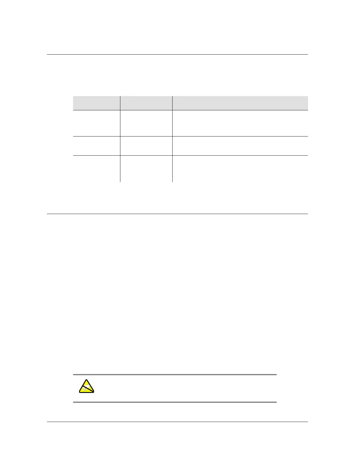
Table 6-4 shows the function of the LED indicators on the front panel of the IMC.
Replacing Output Modules
The TimeProvider supports up to four Output modules on the shelf, and up to four
additional Output modules on the Expansion Panel. A variety of Output modules is
available to support different wiring schemes (see Making Output Connections, on
page 60, for a description of the available Output modules).
To remove an Output module:
1. Disable the outputs on the Output module by issuing the command:
ED-EQPT::OUTg:::OUTSTATE=DISABLE;
where g is the output group you are disabling (A, B, C, or D)
2. Attach a wrist grounding strap and connect it to the TimeProvider chassis.
3. Remove the output connections.
4. Remove the Output module by loosening the captive screws and pulling the
module off the shelf.
5. Place the module in a static-free bag or on a static-free surface.
Table 6-4. LED Conditions for the TPIU
LED Name Condition Description
TPIU Power Green
Off
Interconnection cable is connected
Interconnection cable is disconnected or GPS
input is disabled
Antenna Power Green
Red
TPIU is communicating with Antenna
TPIU has lost communication with Antenna
Antenna Signal Green
Red
Off
Antenna is communicating with the TPIU
Master shelf is powering up
Antenna has lost communication with the TPIU
Warning: To avoid possible electrostatic damage to the Output
module, place it in a static-free bag or on a static-free surface.
 Loading...