097-58001-02 Revision C – August 2005 TimeProvider User’s Guide 55
Chapter 3 Installing the TimeProvider
Making Connections
To install the TimeProvider power connections:
1. Assemble a power connector appropriate for the type of shelf. Table 3-1 lists the
pin-out for each type of connector.
Rear-access shelf: Crimp a No. 16 AWG (minimum) wire (1.31 mm
2
) to each pin,
then slide the pin into the shell.
Front-access shelf: Assemble the power connector as shown in Figure 3-6.
Solder a No. 16 AWG (minimum) wire (1.31 mm
2
) to each pin. Slip the
appropriate grommet over the wires, and screw the shell together.
2. Attach the connector to the Power A and Power B connectors on the shelf.
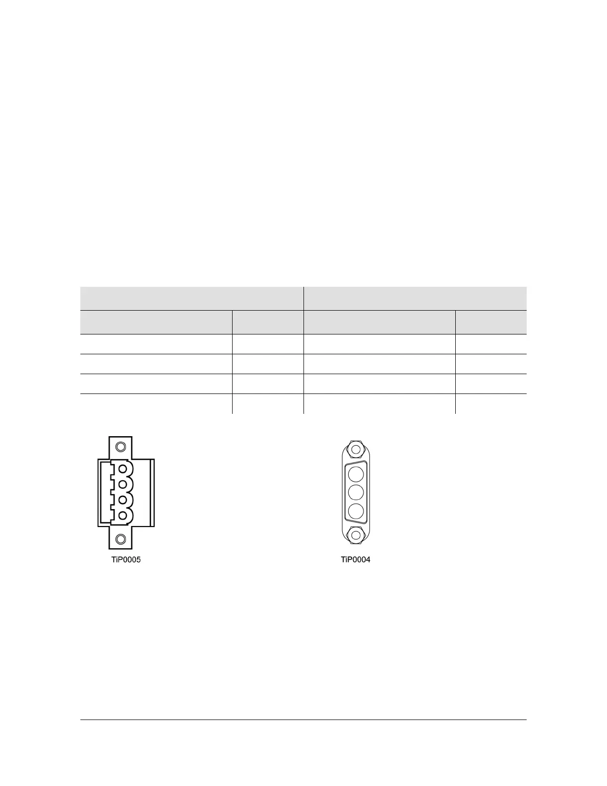
Figure 3-5. Power Terminal Connectors
Table 3-1. Power Connections
Model 1100 Rear Access (NEBS) Shelf Model 1000 Front Access (ETSI) Shelf
Signal Terminal Signal Terminal
48 Volt Negative Lead 1 Frame Ground 1
48 Volt Positive Lead (return) 2 48 Volt Negative Lead 2
Frame Ground 3 48 Volt Positive Lead (return) 3
Unused 4 – –
Pin 1: -48 V DC Battery
Pin 2: -48 V DC RTN
Pin 4: unused
Pin 3: Frame ground
Rear Access Shelf Front Access Shelf
Pin 1: Frame ground
Pin 2: -48 V DC negative lead
Pin 3: Return
 Loading...