Chapter 1 Overview of the TimeProvider
System Power
30 TimeProvider User’s Guide 097-58001-02 Revision C – August 2005
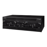
Output Module
The Output module provides the output connectors for the TimeProvider. You can
install up to four Output modules on the main shelf. Like the Input module, each
Output module uses one of a variety of connectors that match the wiring system at
the installation site. Making Output Connections, on page 60, describes the Output
Modules available for the TimeProvider and the Expansion Panel.
Retimer Module
The Retimer module allows you to reshape, reamplify, and retime up to two E1 or T1
signals applied to the module and then deliver the improved signal to a connected
Network Element. You can install a Retimer module in any of the four slots used by
Output modules, but not in the available Expansion Panel. The T1 Retimer supports
line build-out (LBO) of up to 655 ft. Making Retimer Connections, on page 62, and
Provisioning the Retimer Module, on page 112, provide more information on using
the Retimer module.
Expansion Panel
The Expansion Panel provides up to 32 additional outputs that the TimeProvider
can generate. See Expansion Panel, on page 22 and Rack Mounting the Shelf and
Expansion Panel, on page 51 for more information.
TimeProvider Interface Unit
The TimeProvider Interface Unit (TPIU) provides power, communication, and a
composite timing reference signal between the antenna and the TimeProvider main
shelf. During antenna installation, you can use the LEDs on the TPIU to detail the
status of the received power and antenna communication. See Making GPS
Connections, on page 64 for more information.
System Power
The TimeProvider main shelf has redundant –48v DC inputs. The inputs are diode
or’d; in the event that one supply fails, the other takes over. The –48v returns are
isolated from the chassis and circuit grounds. A 5 A fuse on the IOC protects the
TimeProvider; the shelf is protected from damage in case the connections are
reversed.
The power supply range is from –36 to –72 V DC. The power requirements vary
according to the type of IOC installed;
Table 1-1
lists the power requirements.
Table 1-1. Typical Power Consumption
IOC Type
Max Power (W)
per IOC
Typical Power (W)
per IOC
Crystal 40 30
Rubidium 60 40 (70 with two Rb IOCs)
 Loading...