097-58001-02 Revision C – August 2005 TimeProvider User’s Guide 69
Chapter 3 Installing the TimeProvider
Making Connections
7. Using a plumb line or bubble level, ensure the antenna is within 5° of vertical
(perpendicular to the horizon), and tighten the mounting bracket bolts.
8. Bolt the lightning suppressor mounting plate to a flange that is attached to a valid
earth ground. The roof ring ground system, a Central Office grounding plate, and
building structural steel are examples of valid earth ground points. If the
mounting plate cannot be bolted to a valid earth ground, bolt the mounting plate
to a point within 15 feet (4.6 m) of the chosen valid earth ground. If the mounting
plate is to be installed in a nonmetallic junction box, perform the installation and
bolt the assembly near the chosen valid earth ground.
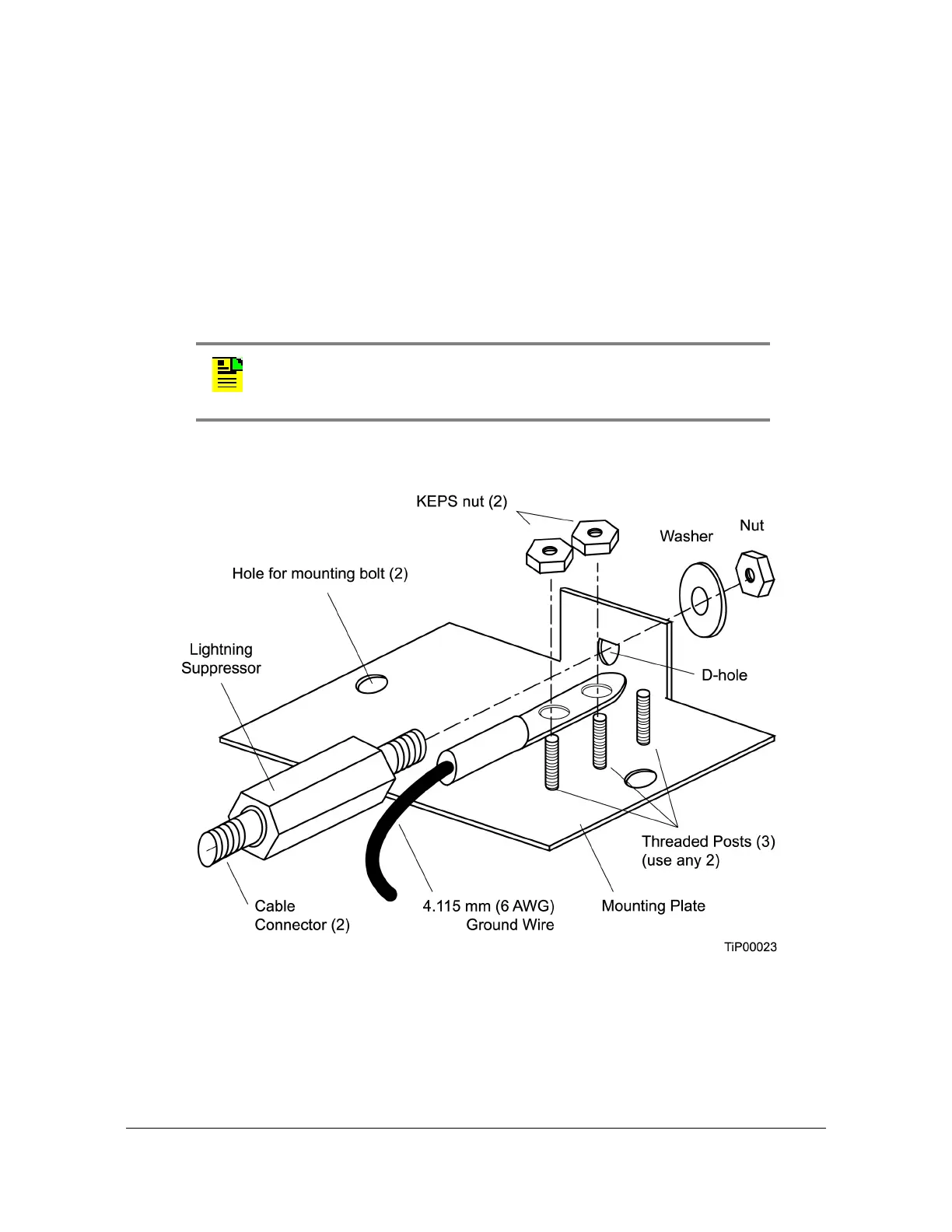
9. Assemble the lightning suppressor as shown in Figure 3-22.
Figure 3-22. Assembling the Lightning Suppressor
10.Install 1.5 inch (3.8 cm) nonmetallic conduit from the antenna to the lightning
suppressor, and from the lightning suppressor to the cable entrance into the
building.
Note: A junction box must have inside dimensions of 7 cm by
7 cm by 4 cm to hold the mounting plate and attached
components.
 Loading...