37
83507013 Rev G
3.7.4 AC Input Wire Connection, 1500W Models
a) Strip the outside insulation of the AC cable approx. 10cm (3.94 inches). Trim the
wires so that the ground wire is 10mm (0.4 inches) longer than the other wires. Strip
14mm (0.55 inches) at the end of each of the wires.
b) Unscrew the base of the strain relief from the helix-shaped body. Insert the base
through the outside opening in the AC input cover and screw the locknut securely
(11-14 Lb-inch.) the base, from the inside.
c) Slide the helix-shaped body onto the AC cable. Insert the stripped wires through the
strain relief base until the outer cable jacket is flush with the edge of the base.
Tighten (16-18 Lb-inch.) the body to the base while holding the cable in place. Now
the cable is securely fastened inside the strain relief. Refer to Fig. 3-2.
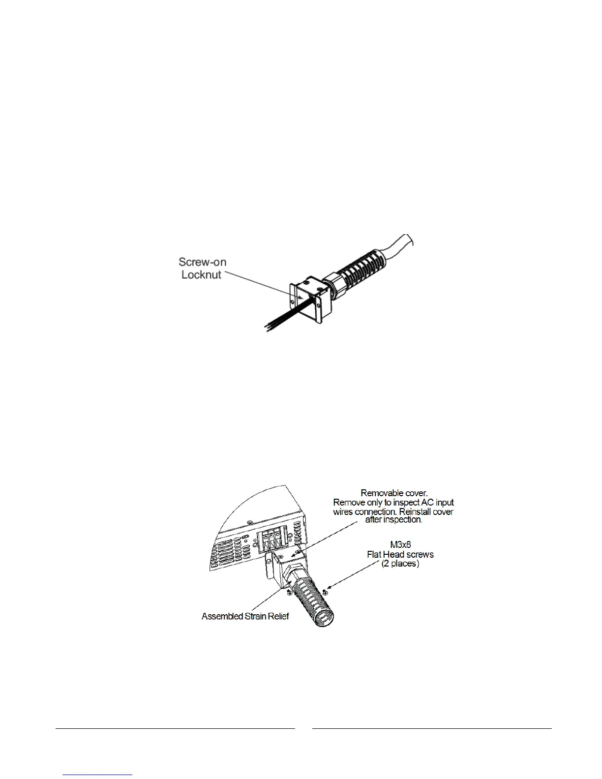
Fig.3-2: Stripped Wires installed in Strain Relief
d) Route the AC wires to the input connector terminals as required. To connect the
wires, loosen the terminal screw, insert the stripped wire into the terminal and
tighten the screw securely (4.4-5.3 Lb-inch).
e) Route the wires inside the cover to prevent pinching. Fasten the cover to the unit
using the M3x8 Flat Head screws provided. Strain relief cover could be opened for
inspection. Refer to Fig.3-3 for details.
Fig.3-3: AC input cover and strain relief, 1500W models
3.8 Turn-On Checkout Procedure
3.8.1 General
The following procedure ensures that the power supply is operational and may be used
as a basic incoming inspection check. Refer to Fig. 4-1 and Fig. 4-2 for the location of
the controls indicated in the procedure.