87
83507013 Rev G
SRQ
Messages
Response
messages
Command Error (”Cnn”)
Execution Error (”Enn”)
Query Response (”message”)
Command Response (”OK”)
CV
CC
NFLT
FLT
AST
FDE
0
LCL
CV
CC
NFLT
FLT
0
0
0
LCL
0
0
0
Status Registers
Condition
Enable
Event
Constant Voltage
Constant Current
No Fault
Fault
Auto Start
Fold Enabled
Spare
Local Mode
0
1
2
3
4
5
6
7
“STAT?”
“SENA xx”
“SENA?”
“SEVE?”
0
AC
OTP
FLD
OVP
SO
OFF
ENA
Fault Registers
Condition
Enable
Spare
AC Fail
Over Temperature
Foldback (tripped)
Over Volt Prot
Shut Off (rear panel)
Output Off (front panel)
Enable Open
0
1
2
3
4
5
6
7
“FLT?”
“FENA xx”
“FENA?”
0
AC
OTP
FLD
OVP
SO
OFF
ENA
Event
“FEVE?”
MSB
MSB
LSB
Serial
TXD
LSB
One response for every command
or query received.
One SRQ when SEVE goes
from all zeroes to any bit set.
Setting more SEVE bits does
not cause more SRQs.
Positive Logic:
0 = No Event
1 = Event Occured
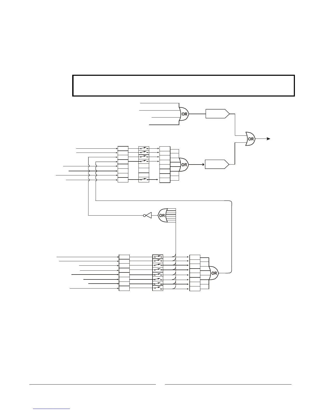
Fig.7-7: Status and Error Registers Diagram
“Inn” and CR
7.11 Status, Error and SRQ Registers
7.11.1 General Description
This Section describes the structure and operation of the six status, error, and SRQ
registers. The registers can be set or red via RS232/RS485 commands.
Refer to Fig. 7-7 for the Status and Error Registers Diagram.
NOTE
These registers operate in a way that is similar to the IEEE-488 and SCPI registers (as used
by the Genesys
TM
with the “-IEMD” option, but the structure and command set is different.
7.11.2 Conditional Registers
The fault Condition Register and the Status Condition Register are read only registers
that the user may read to see the condition of the Power supply. Refer to Table 7-8 for
description of the Fault Condition Register bits and Table 7-9 for the Status Condition
register bits.