44
83507013 Rev G
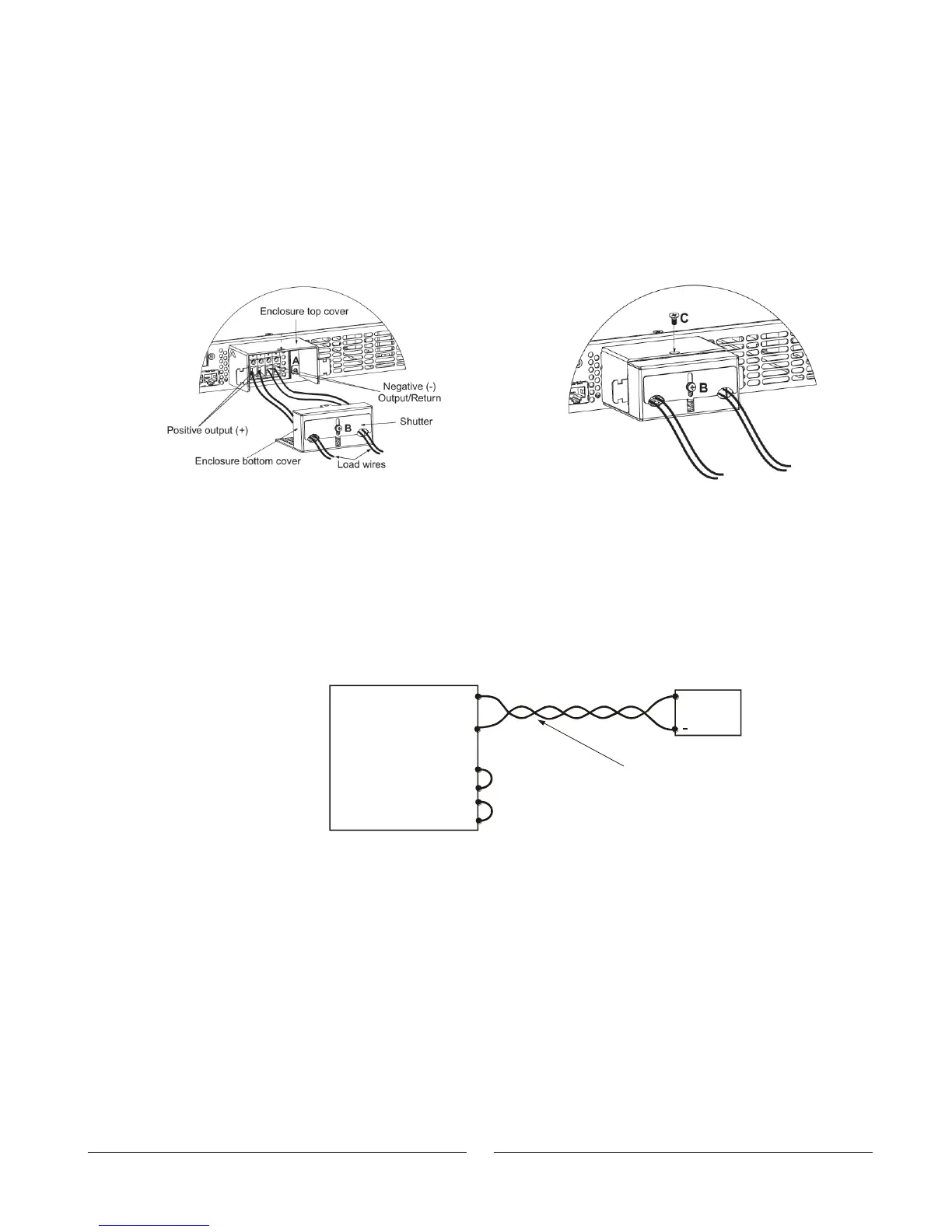
4. Insert the stripped wires into enclosure opening through the shutter and then to the
terminals. Tighten the terminals screws securely. (see Fig.3-8).
5. Loosen the two chassis screws marked “A” halfway.
6. Assemble the enclosure top cover to the chassis and tighten screws “A” (tightening
torque: 4.8-5.3 Lb-inch).
7. Assemble the bottom cover enclosure back to it’s place, as show in Fig. 3-9, using
screw “C”, (tightening torque 4.8-5.3 Lb-inch)
8. Slide down the shutter to secure load wires in place, and tighten screw “B”.
Figure 3-8: Load wires connection to the Fig.3-9: Enclosure assembly
Output connector.
3.9.7 Connecting Single Loads, Local Sensing (default).
Fig.3-10 shows recommended load and sensing connections for a single load. The local
sense lines shown are default connections at the rear panel J2 sense connector. Local
sensing is suitable for applications where load regulation is less critical.
-
-
Rem.sense
Local sense
ocal sense
Rem.sense
+L
+
Load lines, twisted
pair, shortest length
possible.
+V
-V
Load
+
Power
Supply
Fig.3-10: Single load connection, local sensing
Fig. 3-10: Single load connection, local sensing