93
83507013 Rev G
8.3 Isolated Programming & Monitoring Connector
Refer to Table 8-1 for detailed description of the rear panel Isolated Programming &
Monitoring connector. To provide the lowest noise performance, it is recommended to use
shielded-twisted pair wiring.
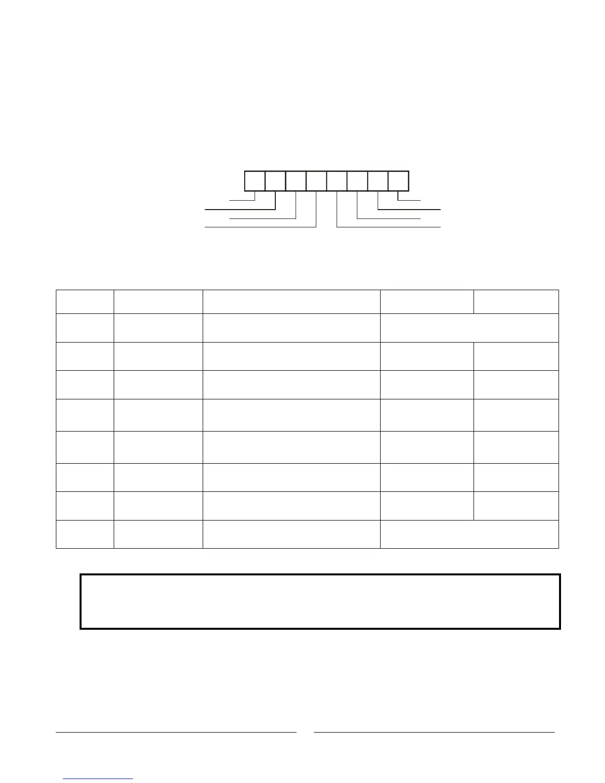
Refer to Fig.8-1 for description of the Isolated Analog Programming & Monitoring connector.
Isolated programming plug P/N: MC1.5/8-ST-3.81, Phoenix.
Table 8-1: Detailed description of Isolated programming & Monitoring connector
Range 0-5/0-10V
IS510 option
Range 4-20mA
IS420 option
Shield, connected internally to chassis of
the power supply.
Output Voltage programming input
Output Current programming input
Ground for programming signals.
Ground for programming signals.
Output voltage monitoring output
Output current monitoring output
Shield, connected internally to chassis of
the supply.
CAUTION
When the Isolated Analog Option is installed, do not apply any signals to the non-isolated VPGM
and IPGM (J1-9 and J1-10) pins. All other J1 features may be used normally. Refer to Section
4.5 for a description of J1 features.
1
2
3
4
5
6
7
8
Shield
+VPROG_ISO
+IPROG_ISO
GND_ISO
Shield
+IMON_ISO
+VMON_ISO
GND_ISO
Fig.8-1: Isolated Programming & Monitoring connector