62
83507013 Rev G
5.14 Series Operation
Power supplies of the SAME MODEL can be connected in series to obtain increased output
voltage. Split connection of the power supplies gives positive and negative output voltage.
CAUTION
Do not connected power supplies from different manufacturers in series or in
parallel.
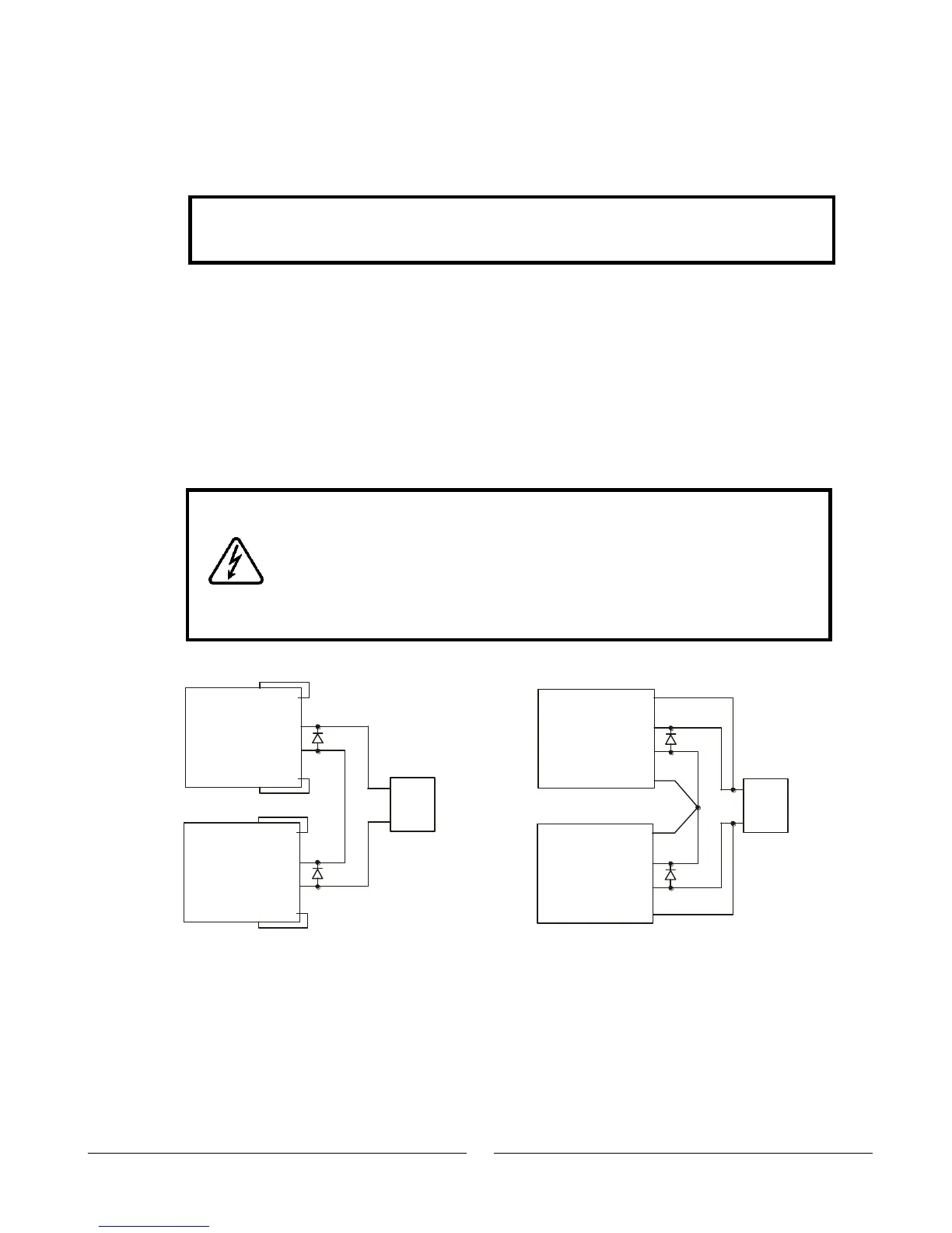
5.14.1 Series Connection for Increased Output Voltage
In this mode, two units are connected so that their outputs are summed. Set the Current
of each power supply to the maximum that the load can handle without damage. It is
recommended that diodes be connected in parallel with each unit output to prevent
reverse voltage during start up sequence or in case one unit shuts down. Each diode
should be rated to at least the power supply rated Output Voltage and Output Current.
Refer to Fig.5-1 and 5-2 for series operation with local and remote sensing.
WARNING
When power supplies are connected in series, and the load or one of
the output terminals is grounded, no point may be at a greater
potential of +/-60VDC from ground for models up to 60VDC Rated
Output and +/-600VDC from ground for models >60VDC Rated
Output. When using RS232/485, LAN or IEEE, refer to the OUTPUT
TERMINALS GROUNDING warning in Section 3.9.11.
+S
+
-
-S
-LS
+LS
POWER
SUPPLY
+S
+
+
-
-
-S
-LS
+LS
POWER
SUPPLY
LOAD
+S
+
-
-S
-LS
+LS
POWER
SUPPLY
+S
+
+
-
-
-S
-LS
+LS
POWER
SUPPLY
LOAD
Fig.5-1: Series connection, local sensing
Fig.5-2: Series connection, remote sensing
(*)
(*)
(*)
(*)
(*) Diodes are
user supplied.