47
83507013 Rev G
3.10.2 Local sensing
The power supply is shipped with the rear panel J2 sense connector wired for local
sensing of the Output Voltage. See Table 3-4 for J2 terminals assignment. With local
sensing, the Output Voltage regulation is made at the output terminals. This method
does not compensate for voltage drop on the load wires, therefore, it is recommended
only for low load current applications or where the load regulation is less critical.
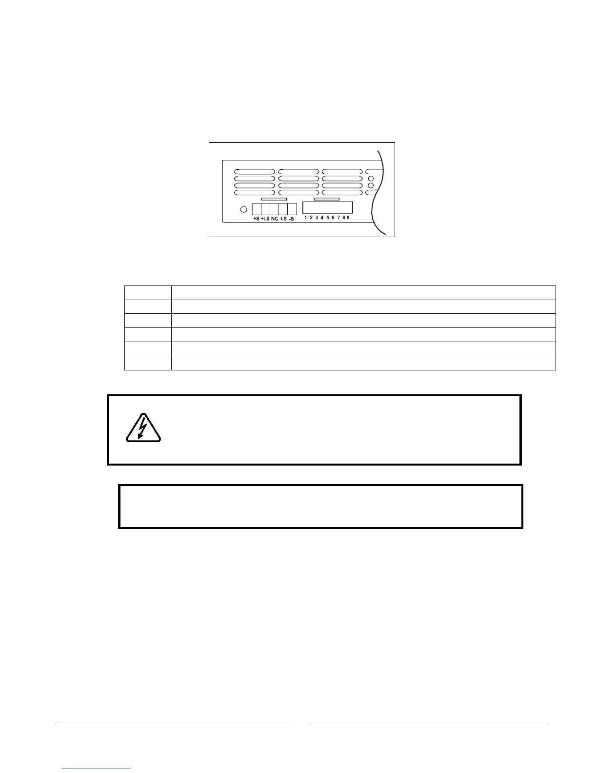
Fig. 3-14: J2 Sense Connector location
Table 3-4: J2 terminals
Remote positive sense (+S).
Local positive sense. Connected internally to the positive output terminal (+LS).
Local negative sense. Connected internally to the negative output terminal (-LS).
Remote negative sense (-S).
3.10.3 Remote sensing
WARNING
There is a potential shock hazard at the sense point when using a
power supply with a rated Output Voltage greater than 40V. Ensure
that the connections at the load end are shielded to prevent
accidental contact with hazardous voltages.
CAUTION
When using shielded sense wires, ground the shield in one place only. The
location can be the power supply chassis or one of the output terminals.
Use remote sense where the load regulation at the load end is critical. In remote sense,
the power supply will compensate for voltage drop on the load wires. Refer to the power
supply specifications for the maximum voltage drop on load wires. The voltage drop is
subtracted from the total voltage available at the output. Follow the instructions below to
configure the power supply for remote sensing:
1. Ensure that the AC On/Off is in the Off position.
2. Remove the local sense jumpers from J2.
3. Connect the negative sense lead to terminal J2-5 (-S) and the positive sense
lead to terminal J2-1(+S) of the J2 mating connector. Ensure that the J2 mating
connector is plugged securely into the rear panel sense connector, J2.
4. Turn On the power supply.
Fig.3-14: J2 Sense connector location
ON
OFF
SW1
J2