52
83507013 Rev G
Table 4-2: Rear panel connections and controls
Wire clamp connector for 1500W units.
IEC connector for 750W units.
Bus-bars for 6V to 60V models.
Wire clamp connector for 80V to 600V models.
RJ-45 type connector, used for connecting power supplies to RS232 or
RS485 port of computer for remote control purposes. When using several
power supplies in a power system, the first unit Remote-In is connected to
the computer and the remaining units are daisy-chained, Remote-In to
Remote-Out.
RJ-45 type connector, used for daisy-chaining power supplies to form a
serial communication bus.
J1 Analog
Remote
connector
Connector for remote analog interface. Includes Output Voltage and
Current programming and monitoring signals, Shut-off control (electrical
signal), Enable/Disable control (dry-contact), Power Supply OK (PS_OK)
signal and operation mode (CV/CC) signal.
Nine position DIP-switch for selecting remote programming and
monitoring modes for Output Voltage, Output Current and other control
functions.
J2 Remote sense
connector
Connector for making remote sensing connections to the load for
regulation of the load voltage and compensation of load wire drop.
Blank sub-plate for standard units. Isolated Remote Analog programming
connector for units equipped with Isolated Analog control option. IEEE
connector for units equipped with IEEE programming option (shown).
Two position DIP-switch for selecting IEEE mode or RS232/485 mode
when IEEE option is installed.
M4x0.7, 8mm long DBL-SEMS screw for chassis ground connection.
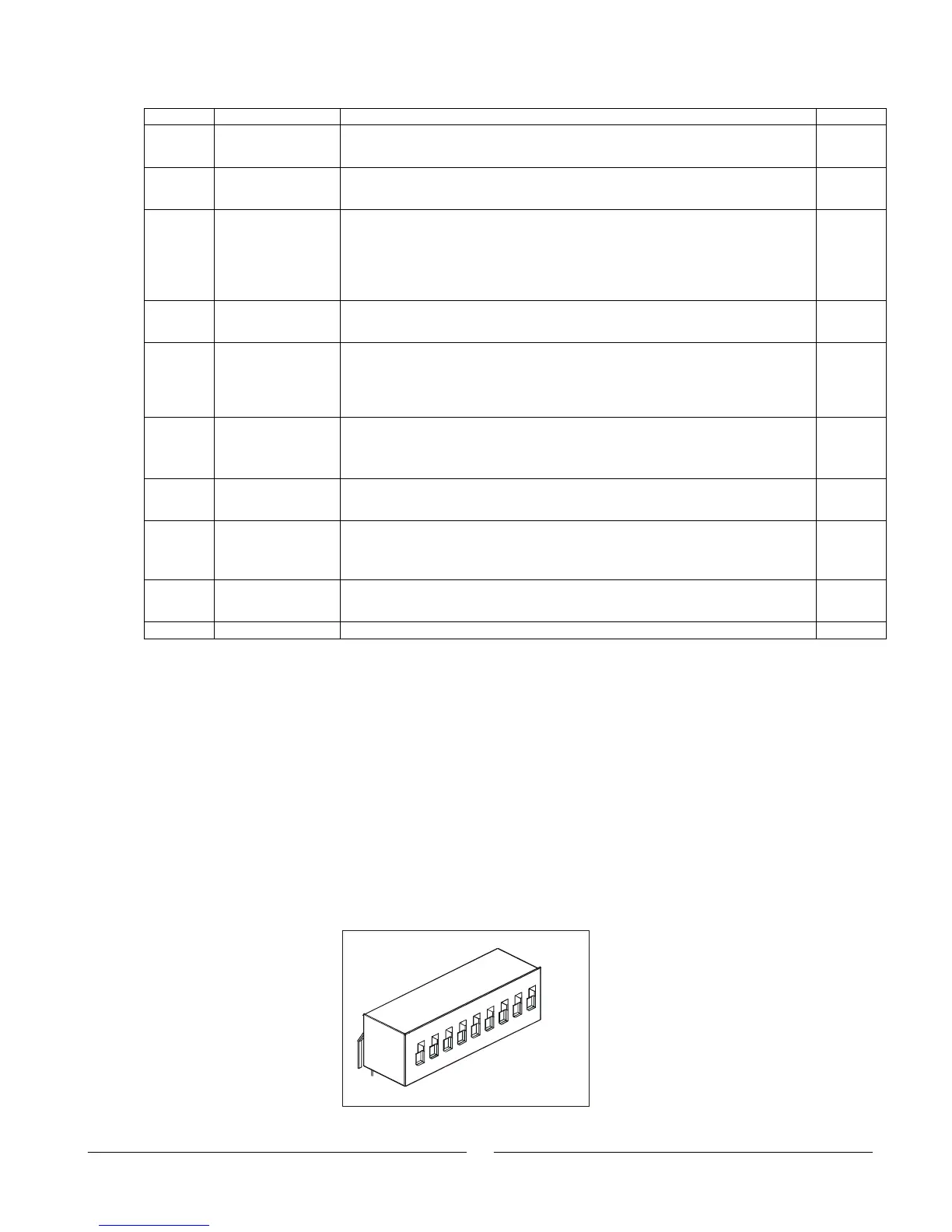
4.4 Rear Panel SW1 Setup Switch
The SW1 Setup switch (see Fig. 4-3) is a 9-position DIP-switch that allows the user to
choose the following:
Internal or remote programming for Output Voltage and Output Current.
Remote voltage or resistive programming of Output Voltage and Output Current limit.
Select range of remote voltage and resistive programming.
Select range of output Voltage and Output Current monitoring.
Select the Remote Shut-Off control logic.
Select between RS232 and RS485 communication interface.
Enable or disable the rear panel Enable/Disable control (dry contact).
Fig.4-3: SW1 setup DIP-switch
1
2
3
4
5
6
7
8
9