51
83507013 Rev G
Main function: Press PREV to display the Output Voltage and
Current setting. For 5 sec. the display will show the setting and
then it will return to show the actual Output Voltage and
Current.
Auxiliary function: Front Panel Lock. Press and hold PREV
button to toggle between “Locked front panel” and “Unlocked
front panel”. The display will cycle between “LFP” and “UFP”.
Releasing the PREV button while one of the modes is displayed
selects that mode.
Green LED, lights when PREV button is pressed.
Voltage and Current Fine/Coarse adjustment control. Operates
as a toggle switch. In Fine mode, the VOLTAGE and
CURRENT encoders operate with high resolution and in Coarse
mode with lower resolution (approx. 6 turns).
Auxiliary function: Set units as Master or Slave in Advanced
parallel operation.
Green LED, lights when the unit is in Fine mode.
Red LED, blinks in case of fault detection. OVP, OTP Foldback,
Enable and AC fail detection will cause the ALARM LED to
blink.
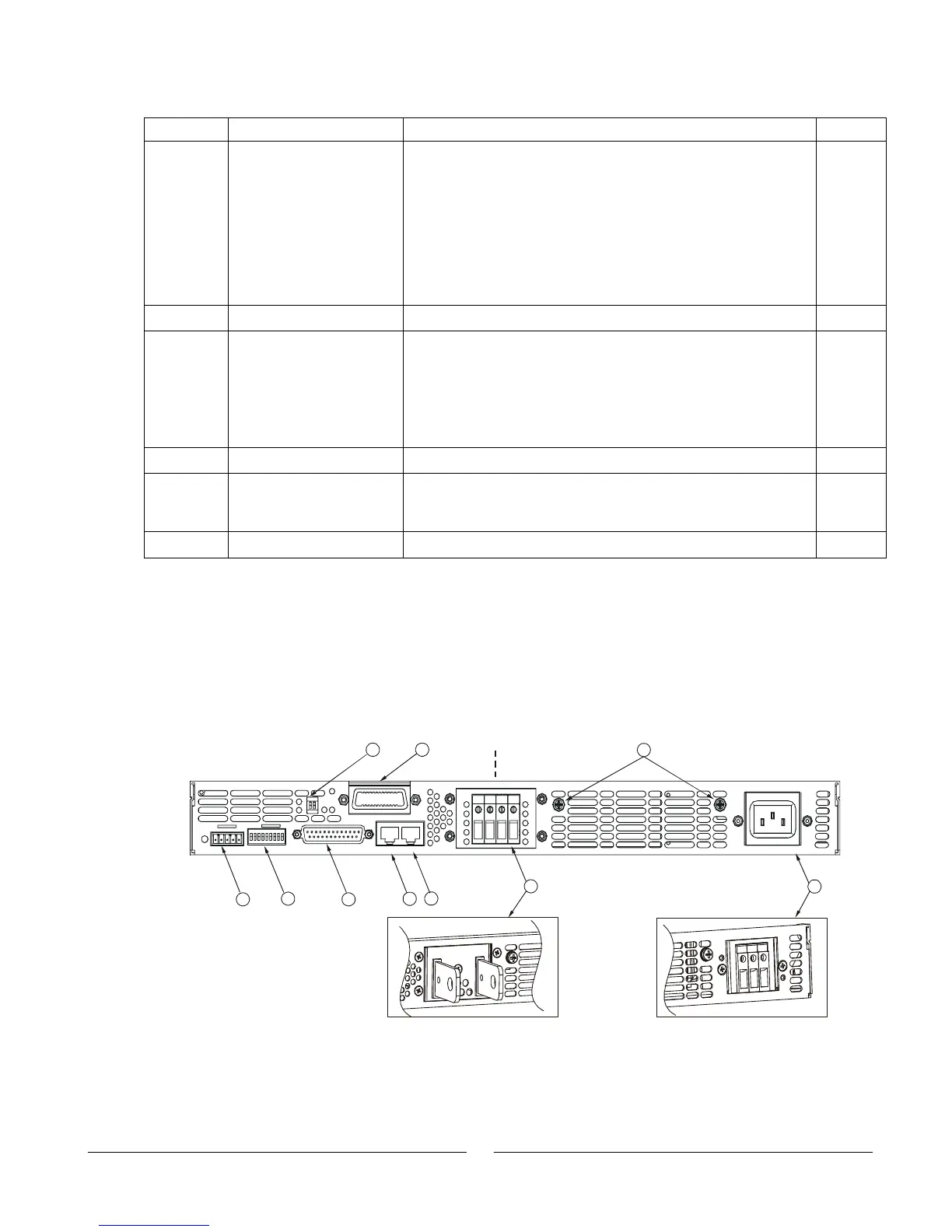
4.3 Rear Panel Connections and Controls
See Fig.4-2 to review the connections and controls located on the power supply rear panel.
Refer to Table 4-2 for explanations about the rear panel connections and controls.
Fig.4-2: Rear panel connections and controls
J2
AC INPUT
ON
OFF
OUT
IN
J3
J1
SW1
10
57
3
89
4
6
1
2
750W
1500W
6~60V
Models
80~600V
Models
+V -V
L
N
G