49
83507013 Rev G
4 FRONT AND REAR PANEL CONTROLS AND CONNECTORS
4.1 Introduction
The Genesys
TM
Power Supply series has a full set of controls, indicators and connectors
that allow the user to easily setup and operate the unit. Before starting to operate the unit,
please read the following Sections for explanation of the functions of the controls and
connectors terminals.
Section 4.2: Front Panel Controls and Indicators.
Section 4.3: Rear Panel Connections and Controls.
4.2 Front Panel Controls and Indicators
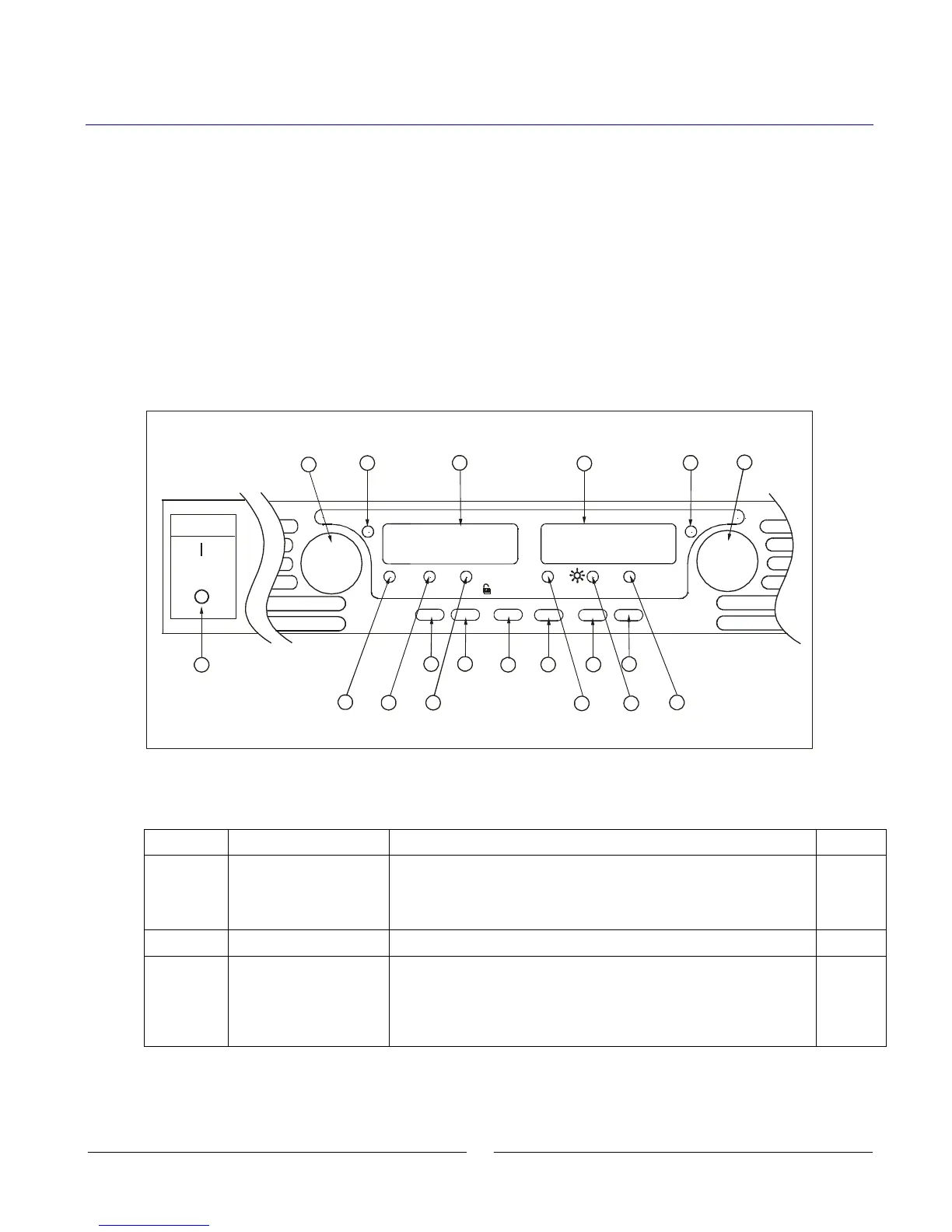
See Fig.4-1 to review the controls, indicators and meters located on the power supply front
panel.
Fig.4-1: Front panel controls and indicators
VOLTAGE
ALARM FINE
PREV/
OVP
UVL FOLD
REM/LOC
OUT
DC AMPS
CURRENT
DC VOLTS
POWER
1
14
17
18
19
2
15
16
3
13
10
4
11
5
12
9
6
7
8
Table 4-1: Front Panel controls and indicators
High resolution rotary encoder for adjusting the Output Voltage.
Also adjusts the OVP/UVL levels and selects the Address
Green LED, lights for constant-Voltage mode operation.
4 digit, 7-segment LED display. Normally displays the Output
Voltage. When the PREV button is pressed, the display indicates
the programmed setting of the Output Voltage. When the
OVP/UVL button is pressed, the Voltage display indicates the
OVP/UVL setting.