59
83507013 Rev G
armed, therefore, if the load current is higher than the current limit setting, the Foldback
protection will be activated again.
Press the FOLD button to cancel the Foldback protection. The power supply output will
be disabled and the VOLTAGE display will show “OFF”. Press the OUT button to enable
the power supply output.
Turn the power supply output Off and then On using the SO control (refer to Section
5.7). In this method the Foldback protection remains armed, therefore if the load current
is higher than the output current setting, the Foldback protection will be activated.
Turn the power supply Off using the AC On/Off switch, wait until the front panel display
turns Off, then turn the unit back ON again. The power supply output is enabled and the
Output Voltage and Current will return to their last setting. In this method, the Foldback
protection remains armed, therefore if the load current is higher than the output current
setting, the Foldback protection will be activated again.
5.6 Output ON/OFF Control
The Output On/Off Enables or Disables the power supply output. Use this function to make
adjustments to either the power supply or the load without shutting off the AC power. The
Output On/Off can be activated from the front panel using the OUT button or from the rear
panel J1 connector. The OUT button can be pressed at any time to Enable or Disable the
power supply output. When the output is disabled, the Output Voltage and Current fall to
zero and the VOLTAGE display shows “OFF”.
5.7 Output Shut-Off (SO) Control via Rear Panel J1 Connector
Contacts 2, 3 and 15 of J1 (Fig.4-2, Item 5) serve as Output Shut-Off (SO) terminals. The
SO terminals accept a 2.5V to 15V signal or Open-Short contact to disable or enable the
power supply output. The SO function will be activated only when a transition from On to Off
is detected after applying AC power to the unit. (Thus, in Auto-Restart mode, the output will
be Enabled after applying AC power; even if SO is at an Off level). After an On to Off
transition it is detected, the SO will Enable or Disable the power supply output according to
the signal level or the short/open applied to J1. This function is useful for connecting power
supplies in a “Daisy-chain” (refer to Section 5.16). The SO control can also be used to reset
the OVP and Fold Protection (refer to Section 5.3 and 5.5 for details).
When the unit is shut-off by a J1 signal, the VOLTAGE display will show “SO” to indicate the
unit state. J1 contact 15 is the SO signal input and contacts 2 and 3, IF_COM, are the signal
return (connected internally). Contacts 2, 3 and 15 are optically isolated from the power
supply output.
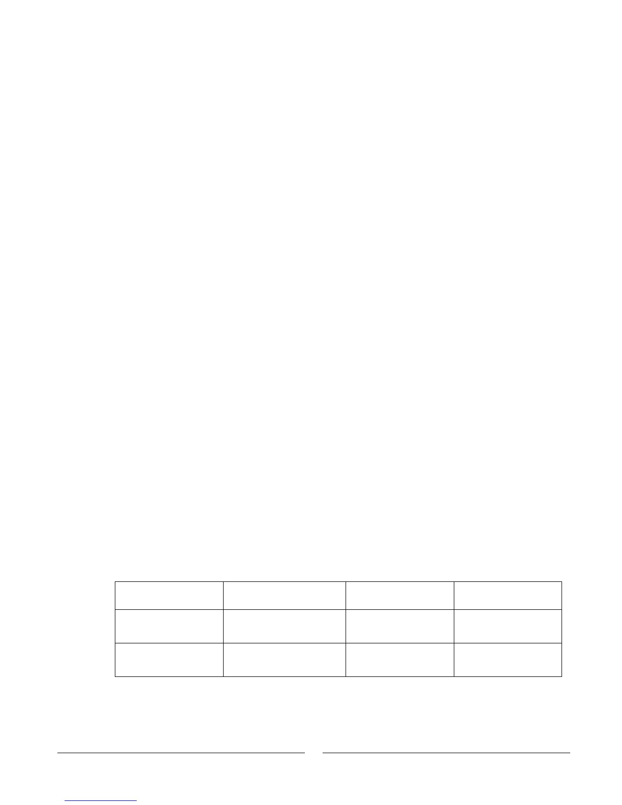
The SO control logic can be selected by the rear panel SW1 Setup switch. Refer to Table 5-
2 for SW1 setting and SO Control Logic.
SO signal level
J1-2(3), 15
2-15V or Open
0-0.6V or Short
2-15V or Open
0-0.6V or Short
Table 5-2: SO logic selection