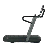
[1]: CHECK THE CORRECT OPERATION OF THE MICROSWITCH.
ATTENTION: The circuit is opened or closed depending on the gradient position of the belt in which
the equipment was blocked.
To perform the check, Insert the tips of the tester in PIN 3 and PIN 8 (brown-blue) of the drive con-
nector, (cable 0WCU0967xx: Reset microswitch cable).
Fig. 42
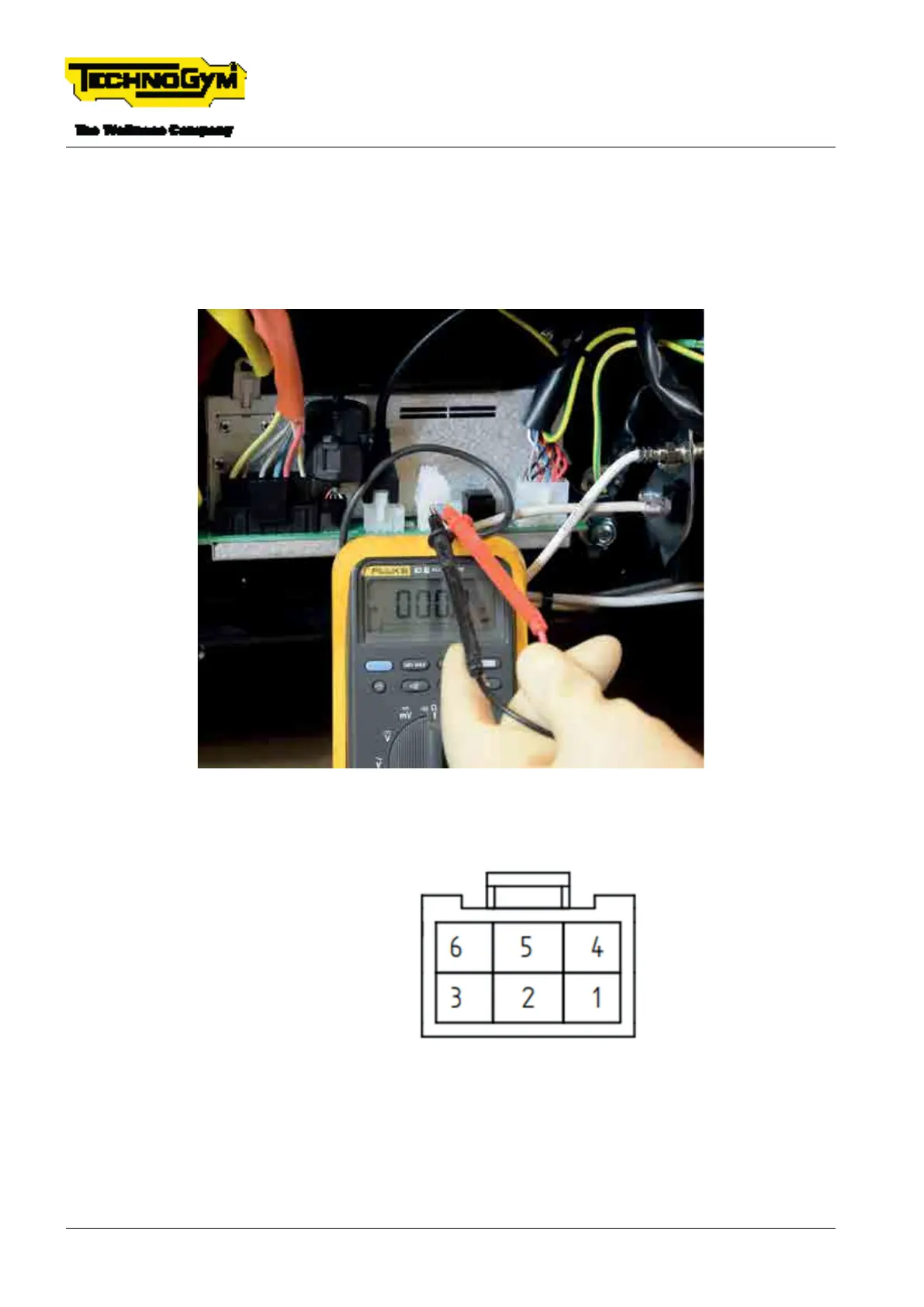
[2]: Gradient motor connector details.
PIN 1 = M+ /BROWN
PIN 2 = M- /BLUE
PIN 3 = nc
PIN 4 = GND-WHITE
PIN 5 = +5V-BROWN
PIN 6 = OUT-GREEN
Fig. 43 - Detailed view of the associated PINs and signals
TECHNOGYM RUN Technical Service Guide
Rev. 1.0
- 86 - TSG-00284-EN- Uncontrolled copy if printed