RUN 600 XTPRO: Service & Maintenance Manual - rev. 1.3
Page 3.10
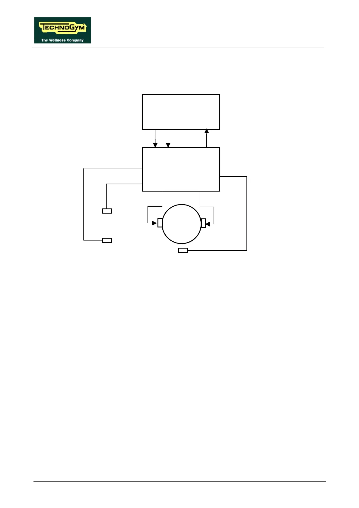
3.3.4. THE SIGNALS INVOLVED
The machine controls the elevation through the CPU board and the elevation interface board as
shown in the figure below:
The elevation control utilizes the following signals:
• Up signal
This is the signal generated by the CPU (pins 10-12 of connector CN1) to enable movement of
the elevation motor in the upward direction. Under normal conditions the signal is at logic level
low (0 Vdc), and it goes high (4.2 Vdc) to actuate the motor. The signal remains high for the
entire duration of the movement.
The signal enters the elevation board (pin 2-4 of connector CN2) and enables movement of the
motor in the desired direction.
• Down signal
This is the signal generated by the CPU (pin 11-12 of connector CN1) to enable movement of
the elevation motor in the downward direction. Under normal conditions the signal is at logic
level low (0 Vdc), and it goes high (4.2 Vdc) to actuate the motor. The signal remains high for
the entire duration of the movement.
The signal enters the elevation board (pin 3-4 of connector CN2) and enables movement of the
motor in the desired direction.
• Motor voltage signal (Vdc)
This is the dc voltage generated by the elevation board (pins 1-2 of connector CN3) to supply
the elevation motor. Its absolute value is 48 Vdc, and the motor will rotate either clockwise or
anticlockwise depending on its polarity. In consequence, the incline of the machine will increase
or decrease.
Photocell
CPU board
10-12
Elevation
board
StatusDown Up
11-12 9-12
2-4
3-4
1-4
CN1
CN2
M
Vdc
Pulses
Switch
3-6
4-6
1-2
2-4/CN1
CN3