RUN 600 XTPRO: Service & Maintenance Manual - rev. 1.3
Page 2.4
2.5.2. WIRING
The high voltage power supply cables and the ground connections are not described here, in that
they can be easily determined from the wiring diagram above.
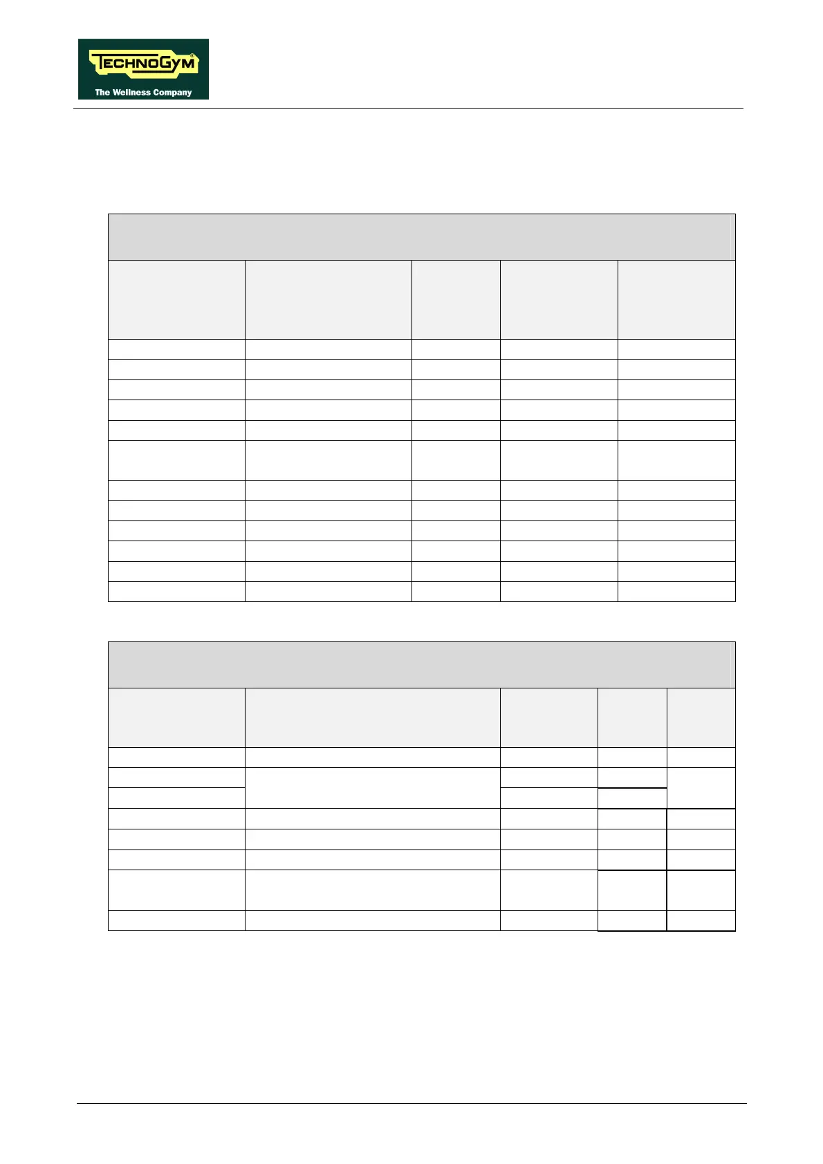
RXIMQ-1: Internal connection cable
CPU board – Inverter interface board – Elevation board
CPU board
CN1
Signal Color Inverter
interface
board
CN2
Elevation
board
CN2
1 +12 Vdc Blue 1 1 -
2 +5 Vdc Brown 1 2 -
3 Ground Gray 1 3 -
4 -12 Vdc White 5 -
5 not used Violet 12 -
6 Tread belt speed
reference (PWM)
Red 10 -
7 Start Black 8 -
8 Inverter alarm Orange 9 -
9 Status Brown 2 - 1
10 Up Pink - 2
11 Down Blue 2 - 3
12 Ground Gray 2 - 4
RX-5/A bis: Inverter cable
Inverter interface board – Inverter – Patch cord
Inverter interface
board
CN1
Signal Color Inverter Patch
cord
CN10
- Thermal cutout Green 3 2
1 White -
-
Thermal cutout Gnd
White P24
1
2 Start Grey 1 -
3 Alarm Blue AL1 -
4 Alarm Gnd Red AL0 -
5 Speed analogue reference (0-10
Vdc)
Brown O -
6 Speed Gnd Black L -