RUN 600 XTPRO: Service & Maintenance Manual - rev. 1.3
Page 2.2
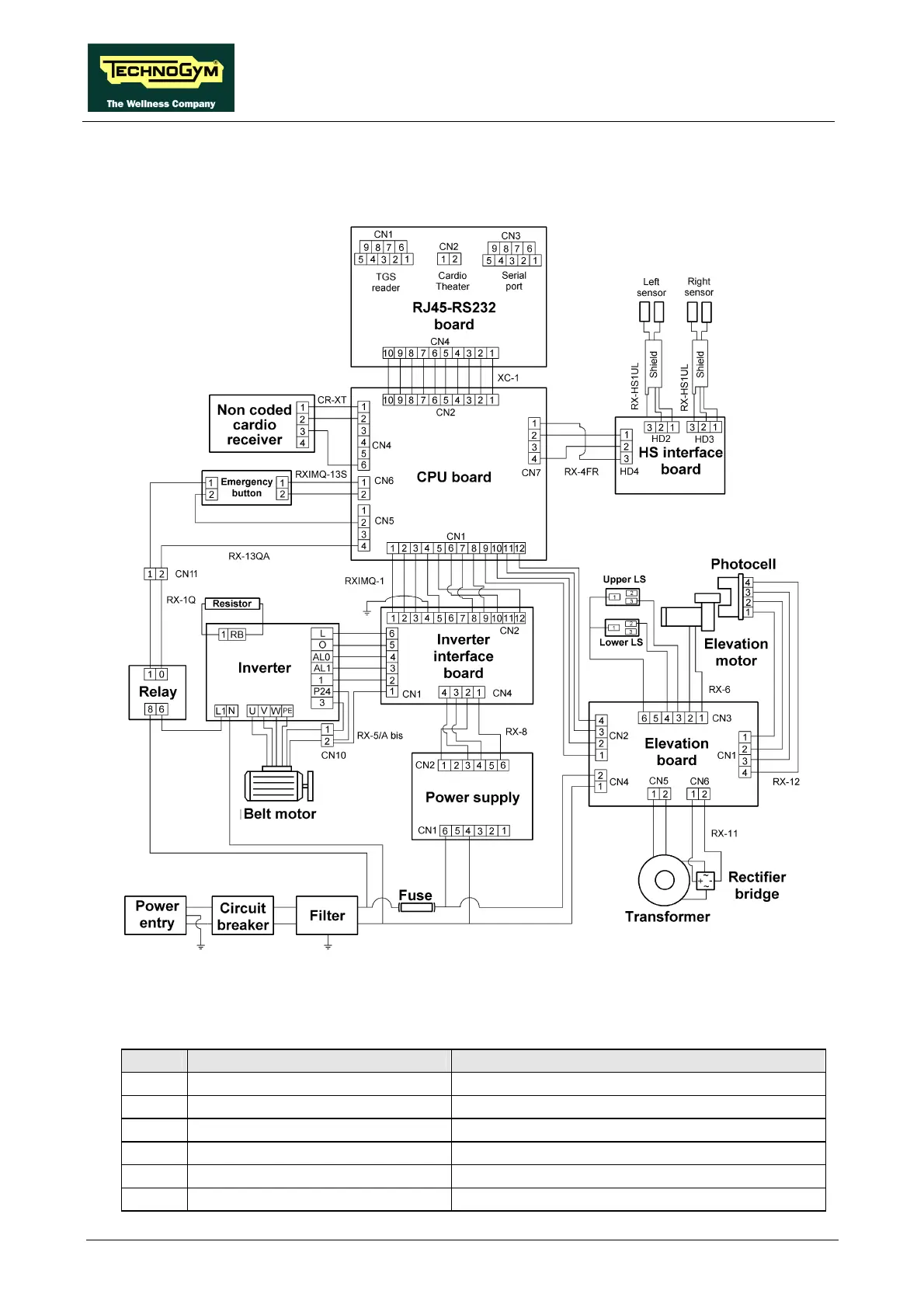
2.5. WIRING DIAGRAM FOR THE 220 MODEL WITH NON-
CODED RECEIVER
2.5.1. CONNECTORS
• CPU board
Name type of connector connection
CN1 AMP MATE-N-LOCK 12 -pin F. to inverter interface board
CN2 Flat 10-pin to RJ45-RS232 board
CN4 AMP MODU II 6-pin M. to cardio receiver
CN5 AMP MODU II 4-pin M. to emergency button
CN6 AMP MODU II 2-pin M. to emergency button
CN7 AMP MODU II 4-pin M. to HS interface board