RUN 600 XTPRO: Service & Maintenance Manual - rev. 1.3
Page 7.31
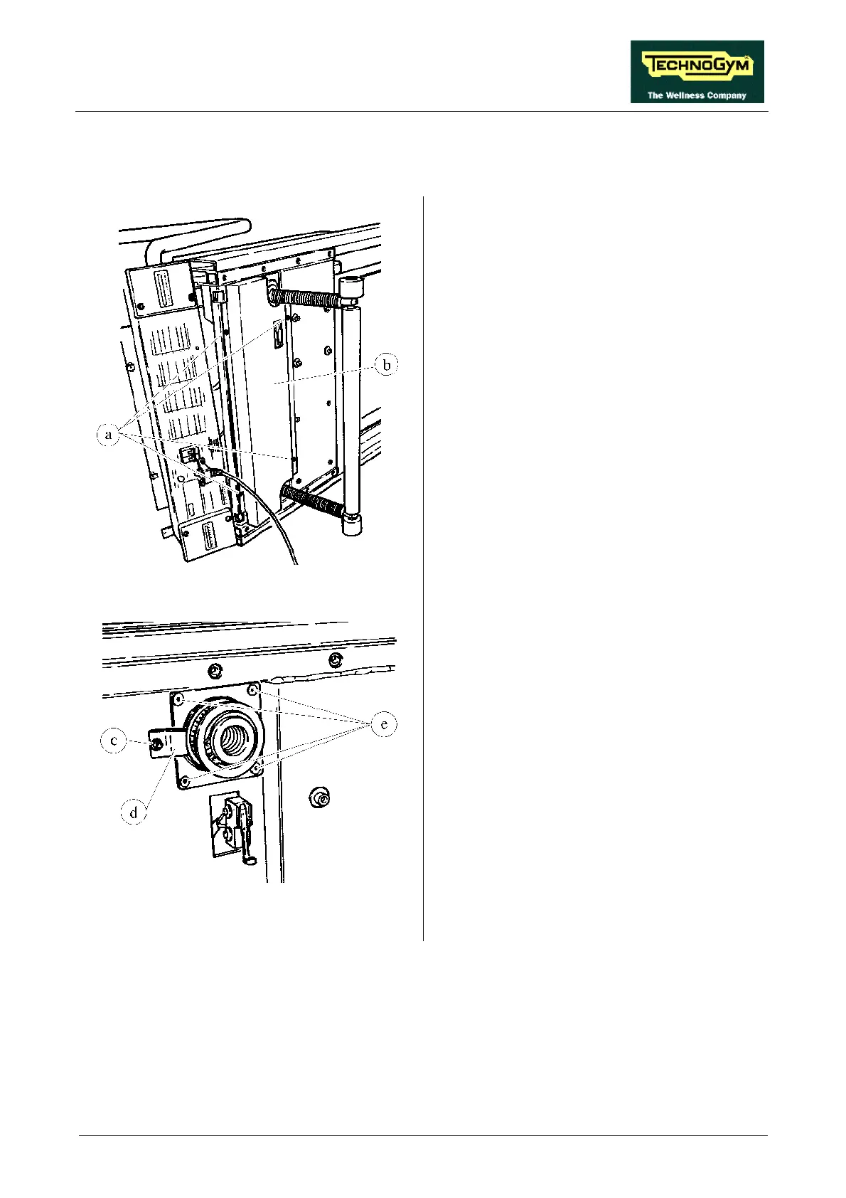
7.20. DISASSEMBLING THE LEAD SCREW NUTS
Figure 7.20-1
1. Set the elevation at 7%.
Carry out the procedures described in paragraphs
7.9. “Disassembling the motor guard” and 7.10.
“Disassembling the front plate”.
2. Overturn the machine on its right hand side.
3. Using a large Phillips screwdriver unscrew
the 4 self-tapping screws a.
4. Remove the belt guard b.
Carry out the procedure described in paragraph
7.19. “Disassembling the elevation bars”.
Figure 7.20-2
5. Back off the bearing clamp screw c using a 4-
mm Allen T wrench.
6. Rotate the clamp d.
7. Unscrew the 4 screws e using a 4-mm Allen
T wrench.
Continued on the following page →