SYNCHRO EXCITE Class & Trend: Service & maintenance manual - rev. 2.0
Page 7.7
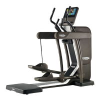
Figure 7.2-10
CPU Board (B):
1. Disconnect the cables indicated in the figure,
coming from TTL Board [CN3], Touch
screen [CN28A], inverter LCD [CN5] and
headphone jack [J3].
ATTENTION: to disconnect the cable
coming from the touch screen, bend
lightly back the protection plate, if
necessary.
2. Back off the 6 screws (e) with a small
Phillips screwdriver.
3. Remove the CPU Board.
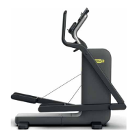
Figure 7.2-11
To disassemble LCD and Touch Screen:
1. Disconnect the cable’s connectors coming
from TTL and Touch screen [CN3-CN28A],
on CPU Board. On the inverter those direct
to the LCD inverter indicated in the figure
[CN2-CN3].
ATTENTION: to disconnect the cable
coming from the touch screen, bend
lightly back the protection plate, if
necessary.
2. Back off the 5 screws (f), which fix the plate
with all the Display Boards, to the front
covering.
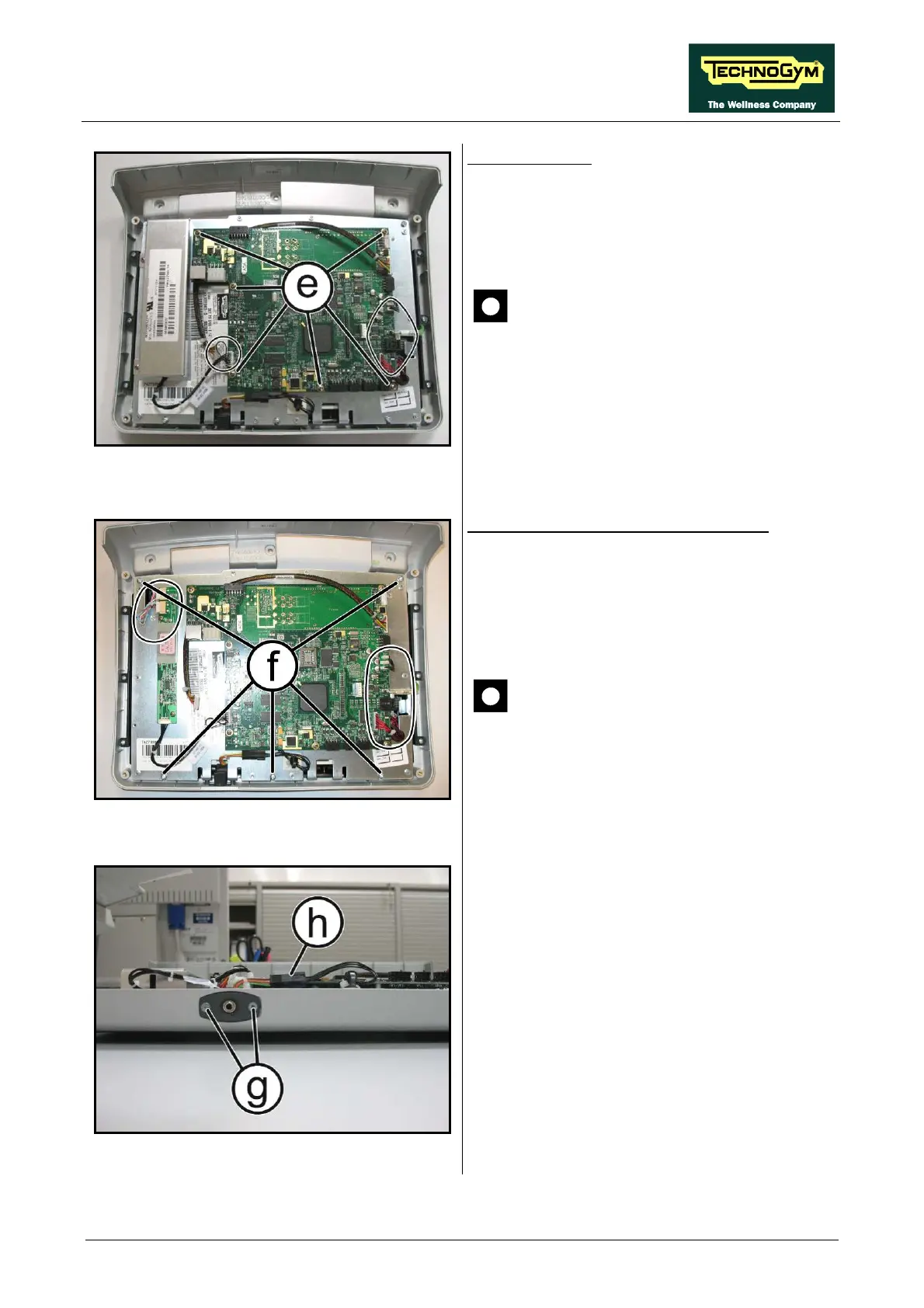
Figure 7.2-12
3. Back off the 2 screws (g) which fix the
headphone jack at the display with a small
Phillips screwdriver.
4. Disconnect the connector (h).
5. Remove the headphone jack from the display
housing.
6. Lift up the plate on which all the circuit
boards and the LCD are fixed.
Continued on following page
→