SYNCHRO EXCITE Class & Trend: Service & maintenance manual - rev. 2.0
Pagina 7.28
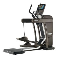
Figure 7.11-7
11. Back off the two screws i using a medium
Phillips screwdriver, while supporting the
lever assembly.
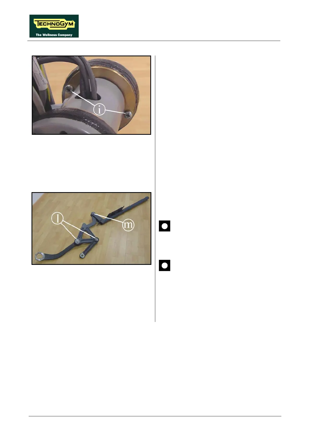
Figure 7.11-8
12. Remove the entire lever assembly from the
machine.
13. It is now possible to disassemble the various
levers and handles, backing off the ring nuts
(l) and (m) with a 20mm and 15mm ring nut
spanner respectively, if necessary holding the
pins in place with an 8mm hexagonal
wrench.
ATTENTION: During reassembly, lock
down the rings (l) using a torque wrench
setting of 70 Nm.
ATTENTION: During reassembly, lock
down the ring (m) using a torque wrench
setting of 50 Nm.
To reassemble the lever, carry out the above
steps in reverse order.
 Loading...