Figure 4-19
4.5.4 Camera Masking
masks lens, the system can alert you to guarantee video
nction.
curred.
r a
in the local host
ail to alert you when alarm occurs.
h as go
nterface is shown as in Figure 4-17.
et
est sensitivity.
vices.
nterface, copy/paste function is only valid for the same type, which means
When someone viciously
continuity. Camera masking interface is shown as in Figure 4-20.
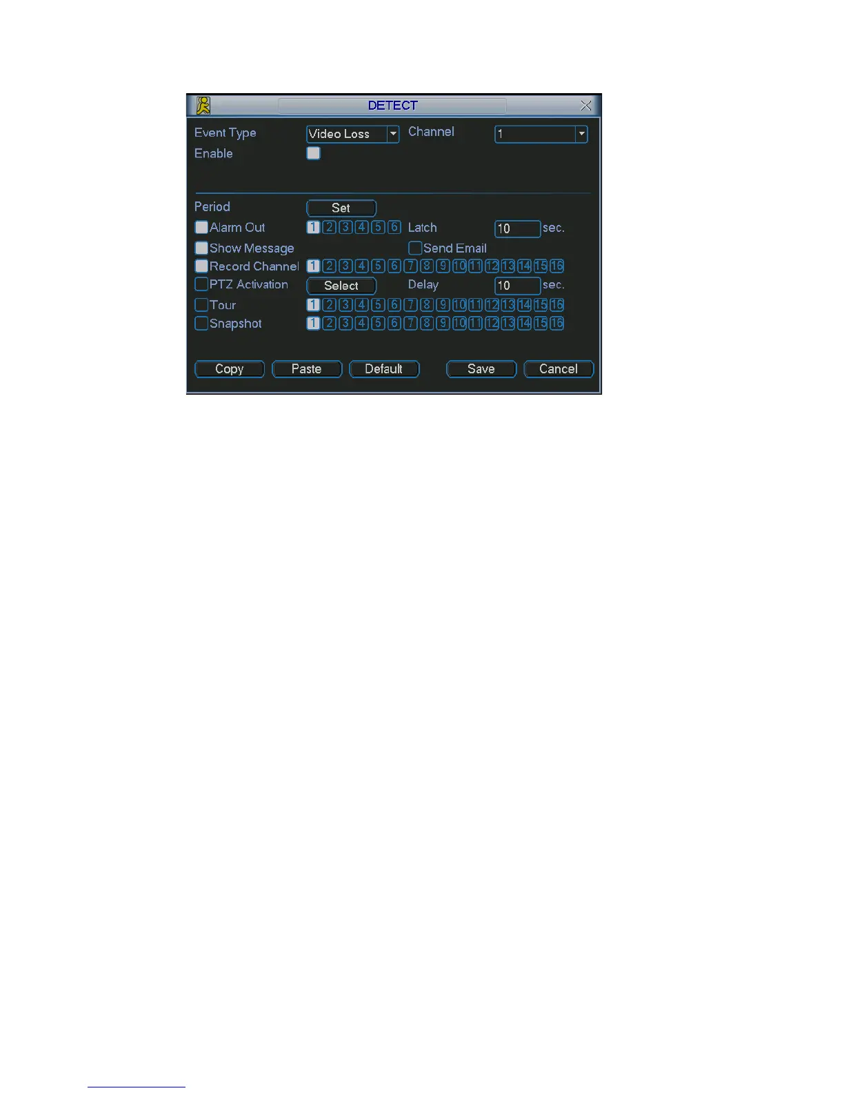
Channel: select the channel you want to enable camera mask detection fu
Event type: please select camera mask detect from the dropdown list.
Channel: select the channel to record when camera mask occurred.
Alarm output: activate peripheral alarm device when camera mask oc
Enable tour: Here is for you to activate tour between different cameras.
Latch: when motion detection complete, system auto delays detecting fo
specified time. The value ranges from 10-300(Unit: second)
Show message: System can pop up a message to alarm you
screen if you enabled this function.
Send email: System can send out em
PTZ activation: Here you can set PTZ movement when alarm occurs. Suc
to preset, tour &pattern when there is an alarm. Click “select” button, you can see
an interface is shown as in Figure 4-16.
Period: Click set button, you can see an i
Here you can set for business day and non-business day. In Figure 4-17, click
set button, you can see an interface is shown as in Figure 4-18. Here you can s
your own setup for business day and non-business day.
Sensitivity: there are six levels. The six-level has the high
Alarm output: when alarm occurred, system enables peripheral alarm de
Tour: Here you can enable tour function when alarm occurs. It is a one-window
tour: Please go to chapter 5.3.9 Display for tour interval setup.
Snapshoot: System can snapshoot when alarm occurs.
Note:
In this i
you can not copy a channel setup in video loss mode to camera masking mode.
46