5-54
5-5 Gain Adjustment
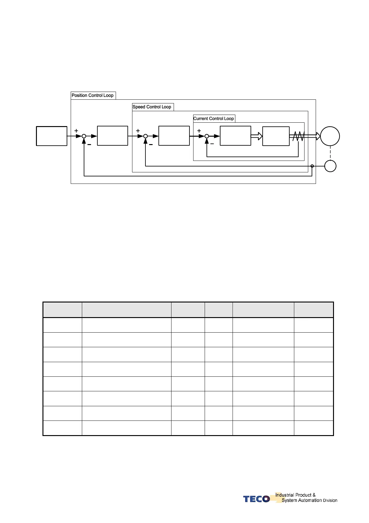
z The Servo controller provides 3 control loops as diagram shown below.
z Control methods are: Current Control, Speed Control and Position Control.
Current
Controllor
Power
Circuit
SM
Speed
Controllor
PG
Position
Controllor
Host
Controllor
z Diagram above shows the three control loops.
z Current (Inner loop), Speed (middle loop) and position (outer loop).
z Theoretically, the bandwidth of inner control loop must be higher than the bandwidth of
the outer control loop, otherwise the whole control system will become unstable, and
cause vibration or abnormal response.
z The relationship between the band width for these three control loops is as follows:
Current Loop (Inner) >Speed Loop (Middle )>Position Loop (outer).
z The default current control bandwidth has already been set for optimum response; so
Only speed and position control loop gains may be adjusted.
z Table below shows the Gain adjustment parameters for the three control loops.
Parameter Name Default Unit Setting Range
Control
Mode
Sn211 Speed Loop Gain 1 40 Hz 10~1500 Pe/Pi/S
Sn212
Speed Loop Integration Time
Constant 1
100
x0.2
msec
1~5000 Pe/Pi/S
Sn213 Speed Loop Gain 2 40 Hz 10~1500 Pe/Pi/S
Sn214
Speed Loop Integration Time
Constant 2
100
x0.2
msec
1~5000 Pe/Pi/S
Pn310 Position Loop Gain 1 40 1/s 1~1000 Pe/Pi
Pn311 Position Loop Gain 2 40 1/s 1~1000 Pe/Pi
Pn312
Position Loop Feed-Forward
Gain
0 % 0~100 Pe/Pi
Cn025 Load Inertia Ratio 10 x0.1 0~1000 Pe/Pi/S

 Loading...
