3-1
Chapter 3 Panel Operator / Digital Operator
3-1 Panel Operator on the Drives
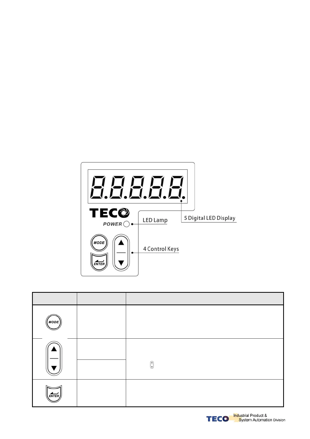
z The operator keypad & display contains a 5 digit 7 segment display, 4 control keys and
two status LED displays.
z Power status LED (Green) is lit when the power is applied to the unit.
z Charge LED (Red) Indicate the capacitor ‘s charge status of main circuit. power on to light
up Charge LED and gradual dark when internal power capacitors are discharged
complete.
z Do NOT wire or assemble to the servo drive before Charge LED is off.
Key Name Function Keys Description
MODE/SET
1. To select a basic mode, such as the status display mode,
utility function mode, parameter setting mode, or monitor
mode.
2. Returning back to parameter selection from data-setting
screen.
INCREMENT
DECREMENT
1. Parameter Selection.
2. To increase the set value.
3. Press
at the same time to clear ALARM.
DATA SETTING
&
DATA ENTER
1. To confirm data and parameter item.
2. To shift to the next digit on the left.
3. To enter the data setting (press 2 sec.)

 Loading...
