5-29
5-4 Position mode
z Position control mode is used for high-precision applications on machinery such as
machine tools.
z The Position control mode offers two methods of control.
¾ External pulse input position command
¾ Internal position command.
z In external pulse command input mode, the positioning command is signaled to the drive
by a host Controller to achieve a fixed position.
z In internal position command mode, 16 preset position commands can be set by
parameters (Pn317~Pn364), and can be activated by use of input contacts POS1 ~
POS5.
z Set parameter Cn001 (control mode selection) as required according to the table below..
Parameter
Signal
Name Setting Description
Control
Mode
Position control (External pulse command)
2
Using one pulse command signal to control position.
Please refer to 5-4-3.
Position control (Internal pulse command)
★●
Cn001
Control mode
selection
6
Use input contacts to select 16 programmable preset
position commands. Please refer to 5-4-2.
ALL
New setting will become effective after re-cycling the power.
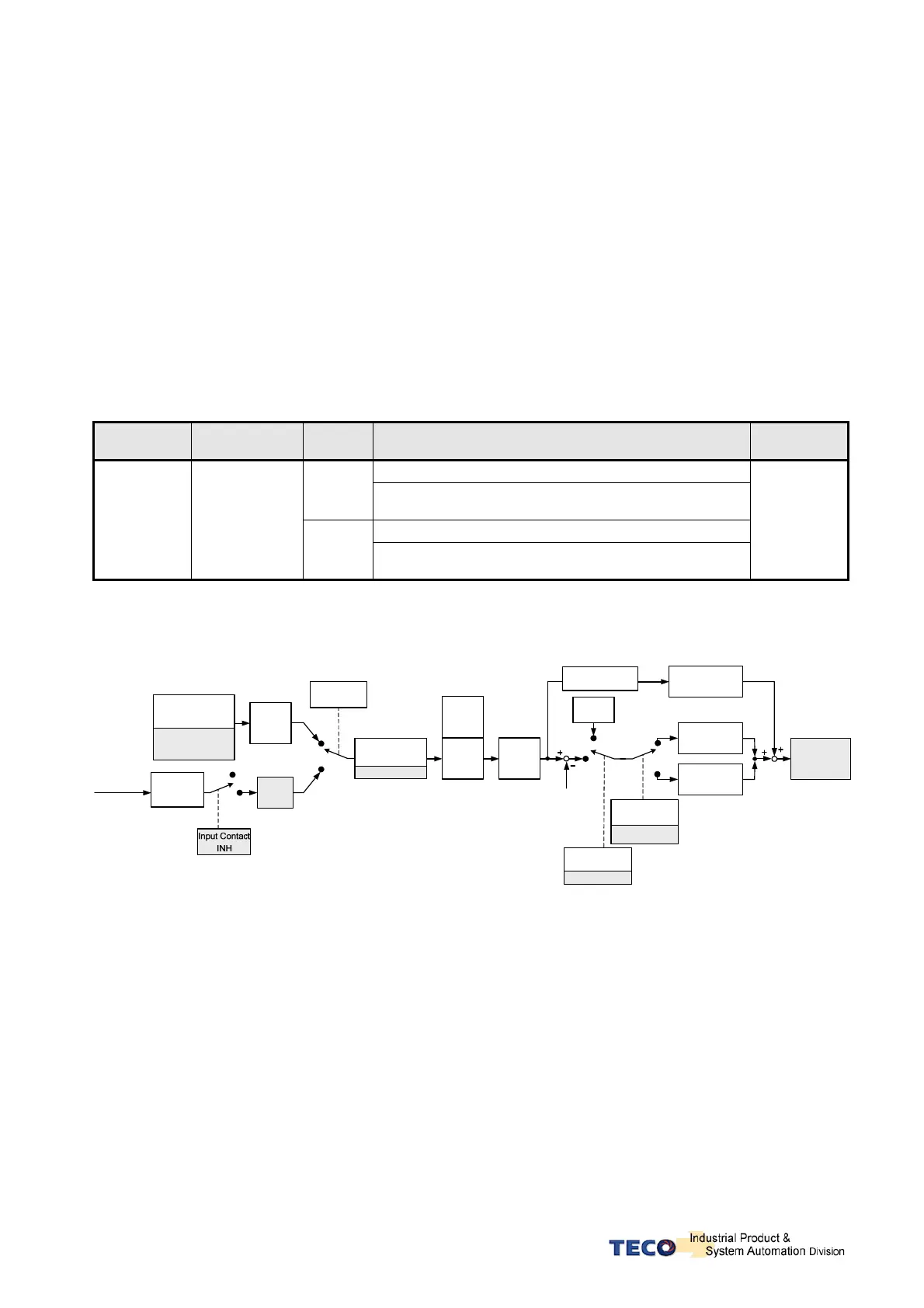
The diagram below shows the position loop control. Detailed functions are described in the following chapters.
Internal Position
Command Mode
Pn316
Counter
External Pulse
Command
Control Mode
Selection
Cn001
Pn313
Position
Command
Direction
Pn314
Motor Position
Feed Back
Position
error set
to 0
Pulse clear mode
Pn315
Input contact CLR
Gain-Switch Method
Cn 015~Cn024
Input Contact
PCNT
Position Rate Gain 2
G- SEL
Pn311
Speed for ward
smooth filter
Cn033
Speed control
loop
Pn302~Pn306
GN1, CN2
Internal position
Command
Cn317~Cn364
Input contacts
POS1~POS4
PTRG, HOLD
Electric Gear
Input Contacts
External pulse
command mode
Pn301
Smooth
AC/ Deceleration
Feed for ward gain
Pn312
Pn310
Position Rate Gain 1
S
Pn322
Pn323

 Loading...
