5-10
5-3-1 Selection for speed command
In Speed control, input contacts SPD1 and SPD2 can be used for selecting one of the two
methods below for setting speed limits.
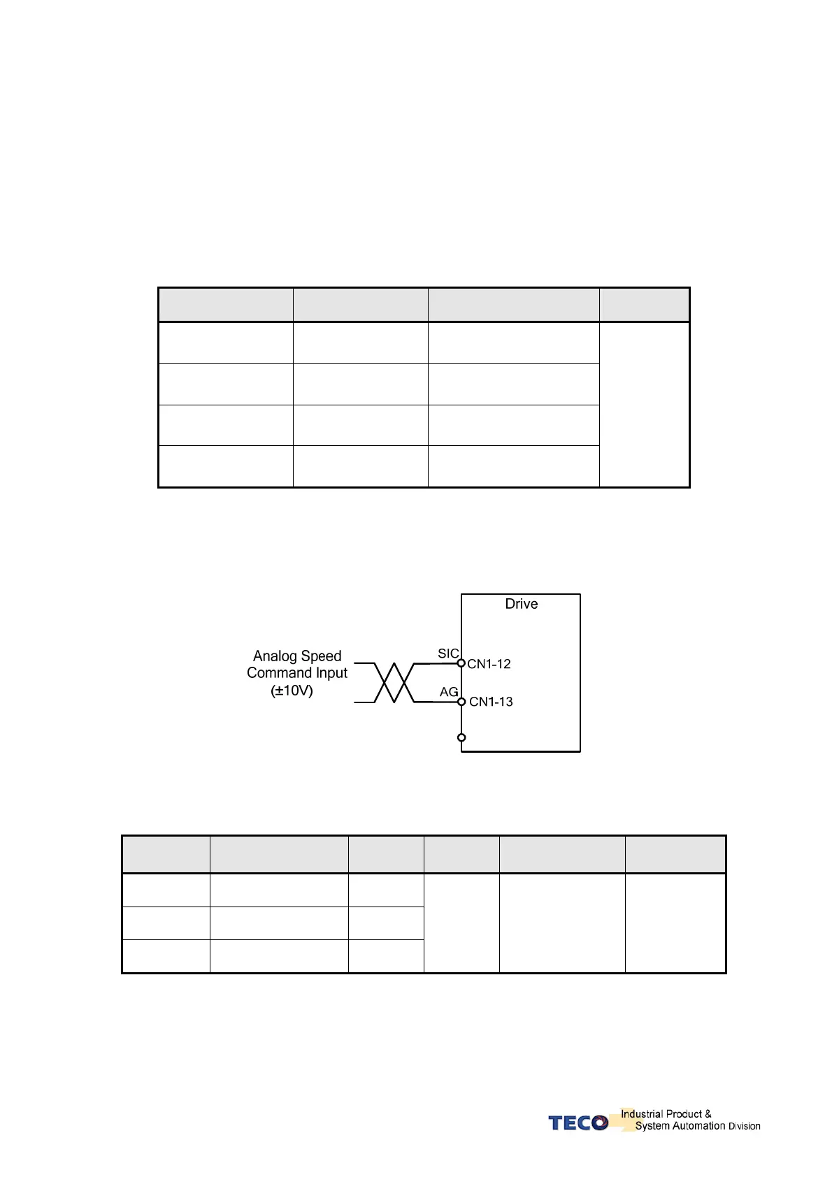
(1) External Analog command (Default) : Analog signal is input from terminals SIC & AG
(pins 12 & 13 on CN1)
(2) Internal speed command: Selection of Three presentable Limits according to the table
below.
.
Input Contact SPD2 Input Contact SPD1 Speed Command
Control
Mode
0 0
External analog command
SIC(CN1-12)
0 1
Internal speed command 1
Sn201
1 0
Internal speed command 2
Sn202
1 1
Internal speed command 3
Sn203
S
Note: Input contacts status “1” (ON) and “0” (OFF).
Please check 5-6-1 to set the required high /Low signal levels (PNP/NPN) selection.
Diagram below shows the external analog speed command wiring:
Internal presetable speed limit parameters for speed command mode are listed below:
These preset limits apply to both CW & CCW directions.
Parameter Name Default Unit Setting range Control mode
Sn201
Internal speed
command 1
100
Sn202
Internal speed
command 2
200
Sn203
Internal speed
command 3
300
rpm -4500~4500 S

 Loading...
