5-7
5-2-5 Internal Torque Limit
In torque Control mode, user can set internal torque limit values as required. Set as below:
Parameter Name Default Unit Setting range Control mode
Cn010
CCW Torque
command limit
300
/
200
% 0~300 ALL
Cn011
CW Torque
command limit
-300
/
-200
% -300~0 ALL
5-2-6 Limiting Servomotor Speed during Torque Control
In torque control, input contacts SPD1 and SPD2 can be used for selecting one of the two
methods below for setting speed limits.
(1) External Analog command (Default) Signal is applied to terminals SIC & AG ( pins
12 & 13 on CN1)
(2) Selection of Three presentable Limits (Tn105~Tn107) according to the table
below.
Caution! For achieving smooth speed response please refer to section 5-3-6.
Input contact SPD2
Input contact
SPD1
Speed limit command
Control
mode
0 0
External analog
command
SIC(CN1-12)
0 1
Internal speed limit1
Tn105
1 0
Internal speed limit2
Tn106
1 1
Internal speed limit3
Tn107
T
Note: Input contacts status “1” (ON) and “0” (OFF).
Please check 5-6-1 to set the required high /Low signal levels ( PNP/NPN) selection.
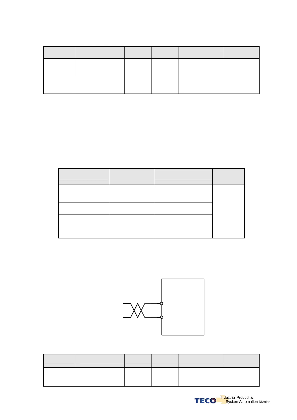
Below is the external analog speed limit command wiring diagram:
CNI-12
Drive
SIC
AG
Analog Speed
Limit Input
(0~10V)
CNI-13
Internal presentable speed limit parameters for torque control mode are listed below:
These preset limits apply to both CW & CCW directions.
Parameter Name Default Unit Setting range Control mode
Tn105 Internal speed limit 1 100 rpm 0~3000 T
Tn106 Internal speed limit 2 200 rpm 0~3000 T
Tn107 Internal speed limit 3 300 rpm 0~3000 T
P.S also refer to page 6-11 for detail.

 Loading...
