5-67
Timing for Brake output signal
Set the required time for the operation of brake output signal (BI) according to the
following.
BI output can be used to control the function of an external electro-mechanical brake.
Parameter Name Default Default Setting Range Control Mode
Cn003
Output time setting for
Mechanical Brake
Signal
0 msec -2000~2000 ALL
Note!
To use brake output signal set Cn008 (Brake mode) to selections 1 or 3 as required.
When the servo system has vertical loading, please set Cn003 to a Positive Number.
For definition of a time value with a positive or a negative sign, refer to the following notes and
timing diagrams.
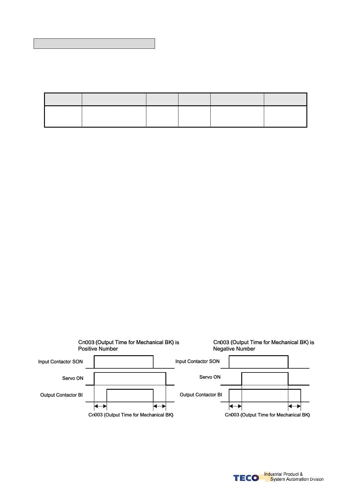
(1) Cn003 set to a time value with a Positive sign.
AS soon as the input contact SON is switched on, Servo on is activated at the same time, and then after
a time delay set by parameter Cn003, Output Contact BI is switched on. (Signal to release the brake).
When SON input contact is switched off, BI output contact is also switched off (Signal to operate the
brake).
Then after a time delay set by parameter Cn003, Servo ON is de-activated.
(2) Cn003 set to a time value with a Negative sign.
AS soon as the input contact SON is switched on, Output Contact BI is switched on at the same time.
(Signal to release the brake). then after a time delay set by parameter Cn003, Servo on is activated.
When SON input contact is switched off, Servo ON is de-activated at the same time.
then after a time delay set by parameter Cn003, Output Contact BI is switched off. (Signal to operate the
brake).
1
1
1
1
1
1
Note: Input contacts status of above time sequence diagram “1” (ON) and “0” (OFF).
Please check 5-6-1 to set the required high /Low signal levels (PNP/NPN) selection.

 Loading...
