5-70
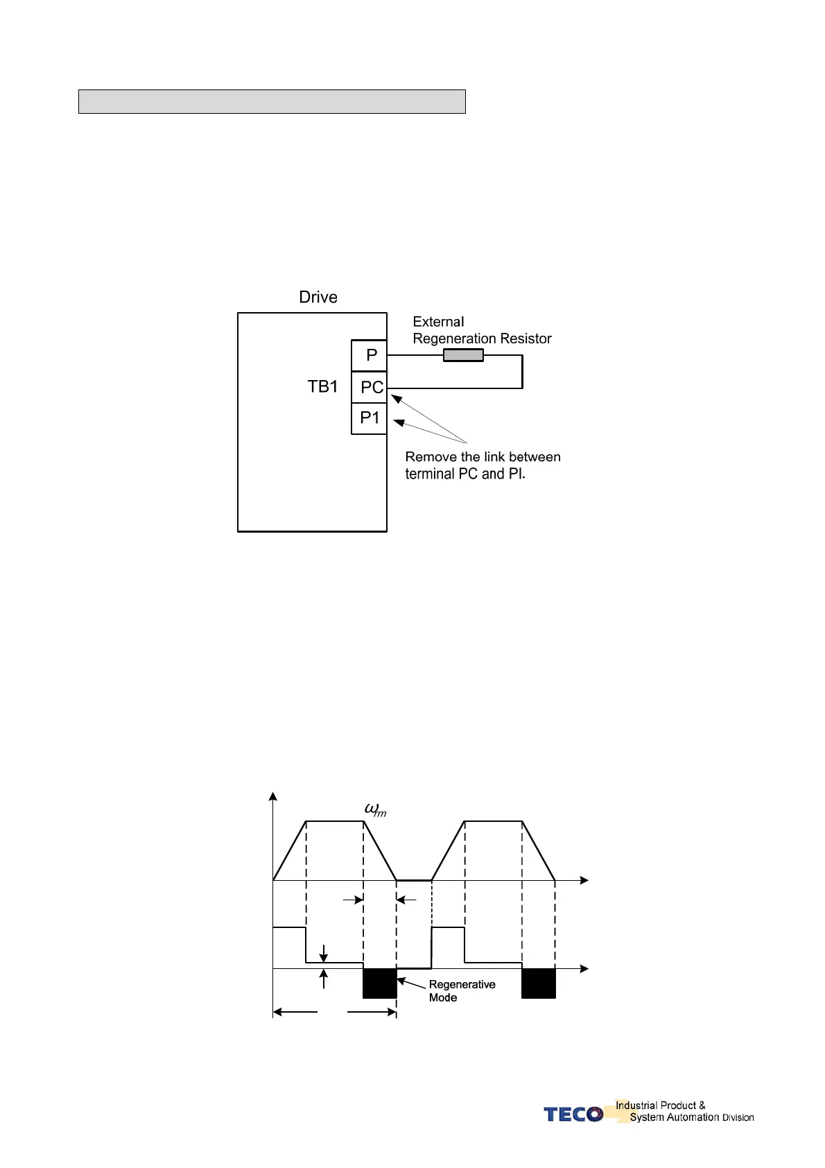
Wiring for External Regeneration Resistor
When external Regeneration Resistor is used, must remove the link between PC and
P1 on TB1 Terminal.
Then the resistor should be installed between terminals P and PC.
For safety, use of resistors with thermal protection is recommended.
The thermal switch contact can then be interlocked to disable drive or remove power
if necessary.
Refer to connection diagram below:
When installing Regeneration Resistors care must be taken as the resistor absorbs
the regeneration power, and it is possible to generate the high temperatures above
100°C.
Provide the necessary cooling and use appropriate high temperature wires and
ensure there has enough space between regeneration resistor and other materials.
Calculation of the external regeneration resistor power (Watts).
Calculate the resistor watts according to the information and formulas below:
(Energy consumed by the motor internally is ignored).
Speed
Time(s)
Running
Speed
Cycle
Torque
D
t
T
L
T
Time(s)
 Loading...

