6-17
Communication
Address
Parameter Name & Function Default Unit
Setting
Range
Control
Mode
RS232 RS485
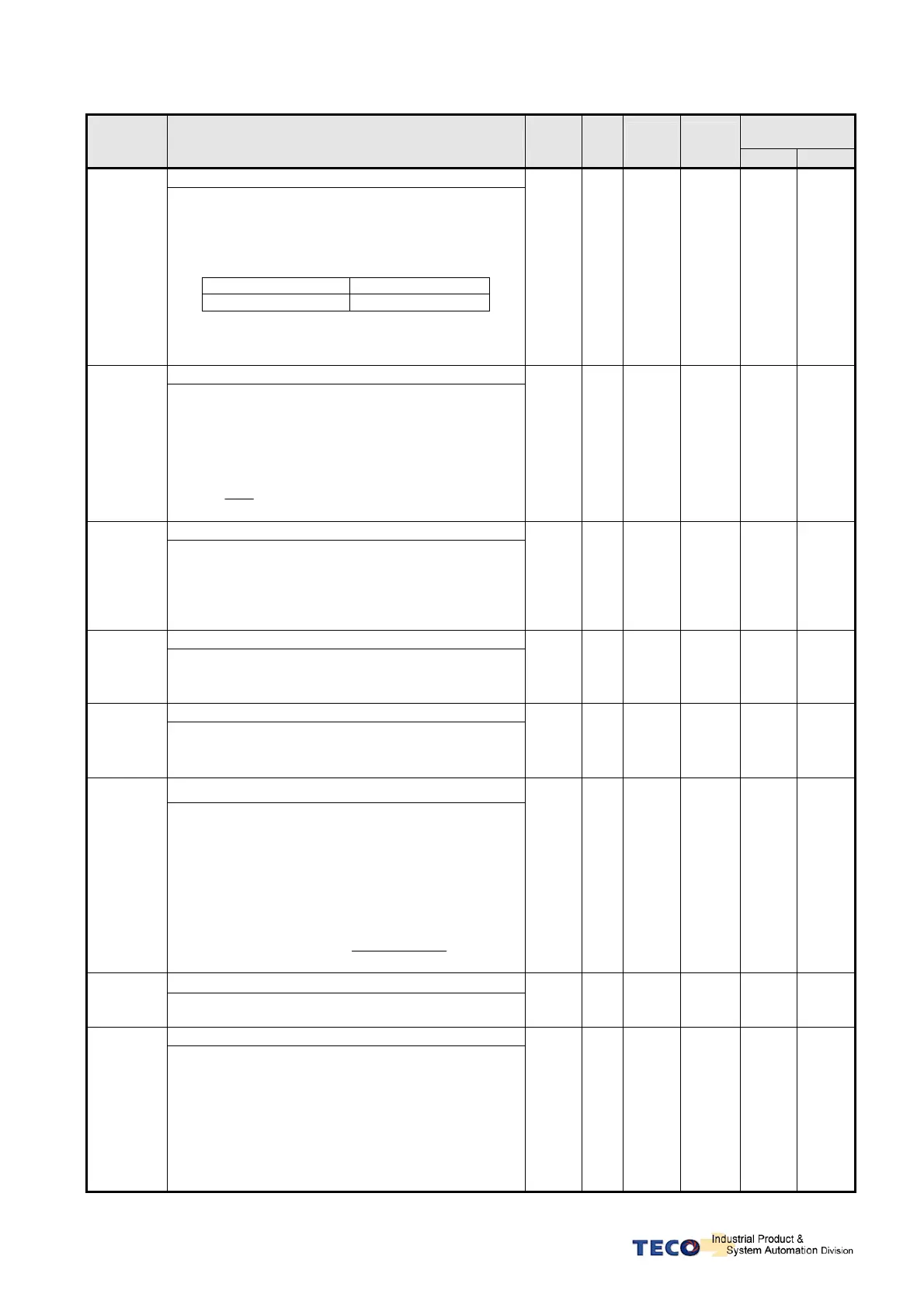
Electronic Gear Ratio Numerator 4
Pn305
Use input contacts GN1 & GN2 to select one of four
electronic Gear Ratio Numerators.
To select Numerator 4, the statue of the
input-contacts
GN1 & GN2 should be as follows:
Input Contact GN2 Input Contact GN1
1 1
Note: Input contacts status “1” (ON) and “0”
(OFF).
Refer to 5-6-1 to set high or low input logic levels.
1 X
1
│
50000
Pi
Pe
563H 0305H
Electronic Gear Ratio Denominator
★
Pn306
Set the calculated Electronic Gear Ratio
Denominator
in Pn 306. ( Refer to section 5-4-3).
Final Electronic Gear Ratio should comply with the
formula below.
020
020
1
≤≤ GearRatioElectronic
1 X
1
│
50000
Pi
Pe
554H 0306H
Position complete value
Pn307
Set a value for In position output signal.
When the Position pulse error value is less then
Pn307
output-contact INP (In position output signal) will
be activated.
10 pulse
0
│
50000
Pi
Pe
552H
553H
0307H
“Incorrect position” Error band Upper limit.
Pn308
When the Position error value is higher then
number of pulses set in Pn308, an Alarm message
AL-11(Position error value alarm) will be displayed.
50000 pulse
0
│
50000
Pi
Pe
556H
557H
0308H
Incorrect position” Error band lower limit.
Pn309
When the Position error value is lower then number
of pulses set in Pn309, an Alarm message
AL-11(Position error value alarm) will be displayed.
50000 pulse
0
│
50000
Pi
Pe
558H
559H
0309H
Position Loop Gain 1
Pn310
Without causing vibration or noise on the
mechanical system the position loop gain value can
be increased to speed up response and shorten the
positioning time.
Generally, the position loop bandwidth should not be
higher then speed loop bandwidth. The relationship
is according to the formula below:
5
2
ainSpeedLoopG
opGainPositionLo ×≤
π
40 1/s
1
│
1000
Pi
Pe
55AH 030AH
Position Loop Gain 2
Pn311
Refer to Pn310
40 1/s
1
│
1000
Pi
Pe
551H 030BH
Position Loop Feed Forward Gain
Pn312
It can be used to reduce the track error of position
control and speed up the response.
If the feed forward gain is too large, it might cause
speed
Overshoot and in position oscillations which result in
the repeated ON/OFF operation of the output
contact
INP(“In Position”output signal).
0 %
0
│
100
Pi
Pe
55BH 030CH

 Loading...
