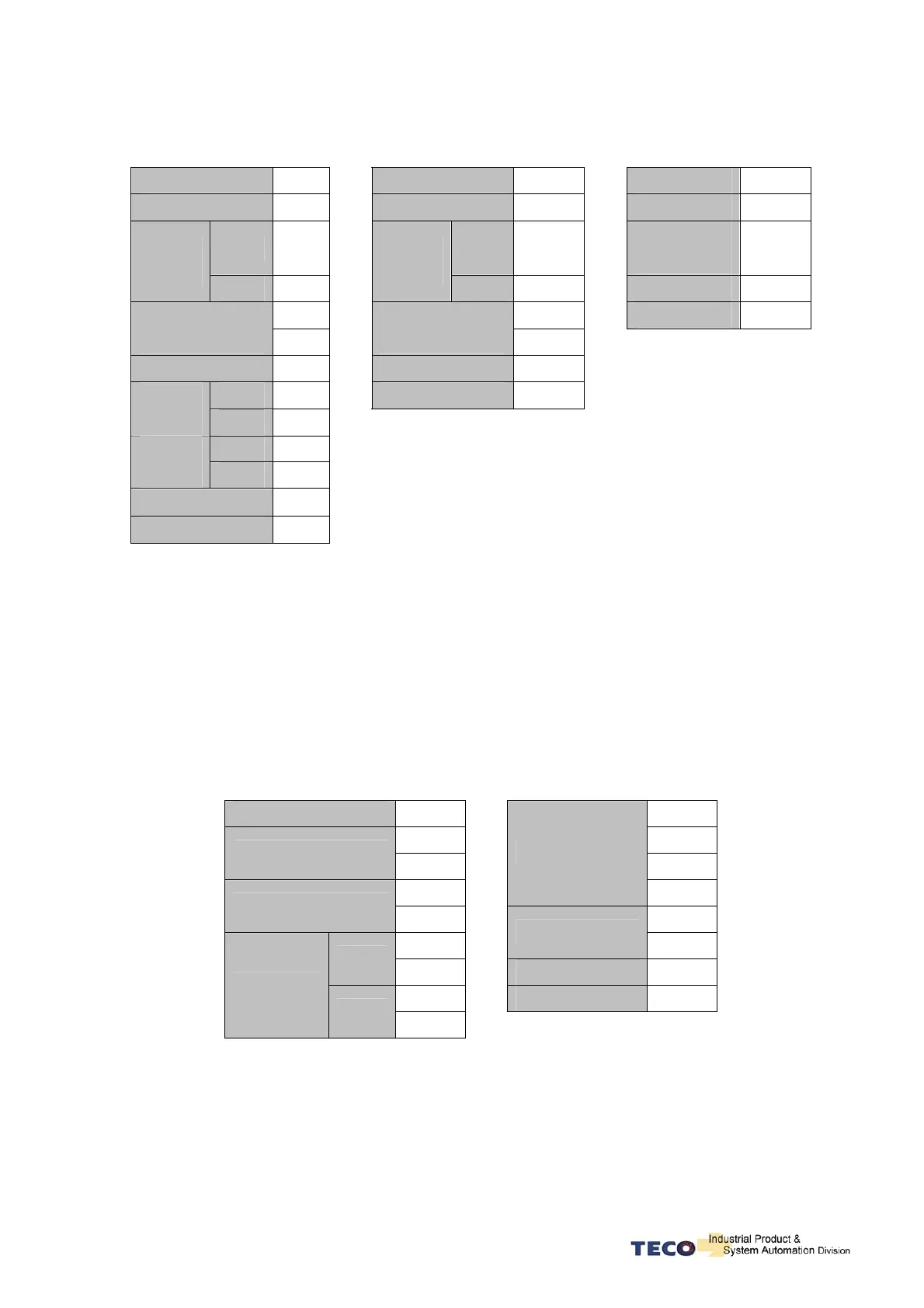
7-14
RTU Mode
Query PC Æ Servo
Response Servo ÆPC (OK)
Servo Æ PC (ERROR)
ADR 01H
ADR 01H
ADR 01H
Function Code
10H
Function Code
10H
Function Code
90H
(HI) 01H
(HI) 01H
Exception
code
02H
Register
ADD
(Lo) 00H
Register
ADD
(Lo) 00H
CRC(Lo) CDH
00H
00H
CRC(Hi) C1H Data length
(word)
02H
Data length
(word)
02H
Byte counters 04H
CRC(Lo) 40H
(HI) 00H
CRC(Hi) 34H
Data
0100H
(Lo) 64H
(HI) 01H
Data
0101H
(Lo) 2CH
CRC(Lo) BFH
CRC(Hi) ADH
LRC (ASCII Mode ) and CRC (RTU Mode) Check methods
LRC Checking:
ASCII Mode LRC (Longitudinal Redundancy Check) checking method
The LRC is calculated by adding together successive 8–bit bytes of the message, discarding any
carries.
Ex. add ADR, Function code, register address and data contents together, if it get the sum 19DH then
discard carrier ”1” and find two’s complement for 9DH to obtain LRC code.
Ex: Execute diagnostic function for Servo drive ID =01H
STX ‘ : ’ ‘ A ’
‘ 0 ’ ‘ 5 ’
ADR
‘ 1 ’ ‘ 3 ’
‘ 0 ’
Data (word)
‘ 7 ’
Function code
‘ 8 ’ ‘ 1 ’
‘ 0 ’
LRC
‘ B ’
(HI)
‘ 0 ’
END1 (CR) (0DH)
‘ 0 ’ END0 (LF) (0AH)
Sub-function
(Lo)
‘ 0 ’
01H+08H+00H+00H+A5H+37H = E5H
Two’s complement for E5H is 1BH ; derive LRC code: ‘ 1 ’ , ‘ B ’

 Loading...
