2-12
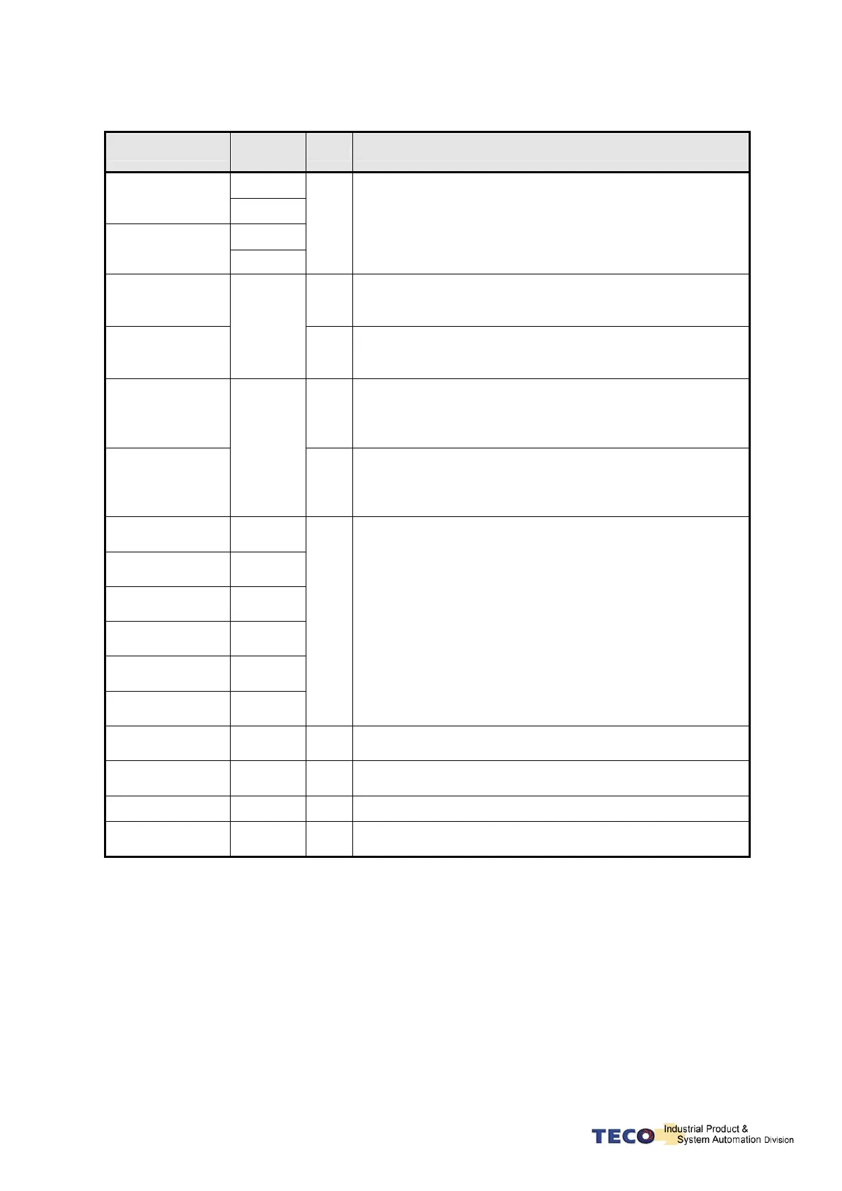
Explanation of General I/O Signal Function
Signal Name
Function
Symbol
Mode I/O Operation and Function
Pulse
Position Pulse
Command Input
/Pulse
Sign
Position Sign
Command Input
/Sign
Pe
The Driver can receive 3 kinds of Command below:
. (Pulse)+ (Sign)
. (CCW)/ (CW)Pulse
.AB Phase pulse
Speed Analog
command Input
S
In Speed Mode, when external speed command is operated
at SPD1=0, SPD2=0, input the voltage range: -10V~+10V,
Sn216 can be set input voltage: ±10V’s Motor output speed.
Torque Analog
Command Input
SIC
T
In Torque Mode, input the voltage range -10~+10V, Tn103
can be set input voltage ±10V’s motor output torque.
Torque Control
Speed Limit
Command
T
In Torque Mode, when external speed limit is operated at
input connect point SPD1=0 & SDP2=0(P.S), input voltage
range: 0~+10V, 10V’s speed limit stands for motor’s ratio
speed.
Position/Speed
Torque Limit
Command
TIC
Pi
Pe
S
In Speed Mode, when external torque limit is be used at input
connect point TLMT=1(P.S.) , input voltage range: 0~+10V,
to input 10V will limit the motor CCW torque is 300% of rate
torque.
Encoder Output A
Phase
PA
Encoder Output /
A Phase
/PA
Encoder Output B
Phase
PB
Encoder Output /
B Phase
/PB
Encoder Output Z
Phase
PZ
Encoder Output /
Z Phase
/PZ
ALL
Outputting the Motor Encoder Signal through pulse per
rotation handle. The pulse quantity of every rotating can be
set in Cn005.
When “1” is set in Cn004, it is CCW rotation from the motor
load terminal direction, and A Phase gets 90 degree ahead B
Phase.
Signal Output is Line Driver.
Analog Signal
Ground Terminal
AG ALL Analog signal grounding: CN1 - > Pin 12, 25.
Digital input COM
Terminal
DICOM ALL Digital input power supplement common terminal.
+24V PW Output IP24 ALL +24V power output terminal(Max. 0.2A).
+24V PW Ground
Terminal
IG24 ALL +24V power grounding terminal
P. S .: “1” stands for “close loop with IG24”; “0” stands for “open loop with IG24”.
PW is abbreviation of Power

 Loading...
