2-13
(b) Digital I/O Signal:
For many kinds of application, the digital input/output terminal layouts of all operation modes are
accordingly different. In order to provide more functions, our drives can provide multi terminal layout settings.
Users can set these functions for application.
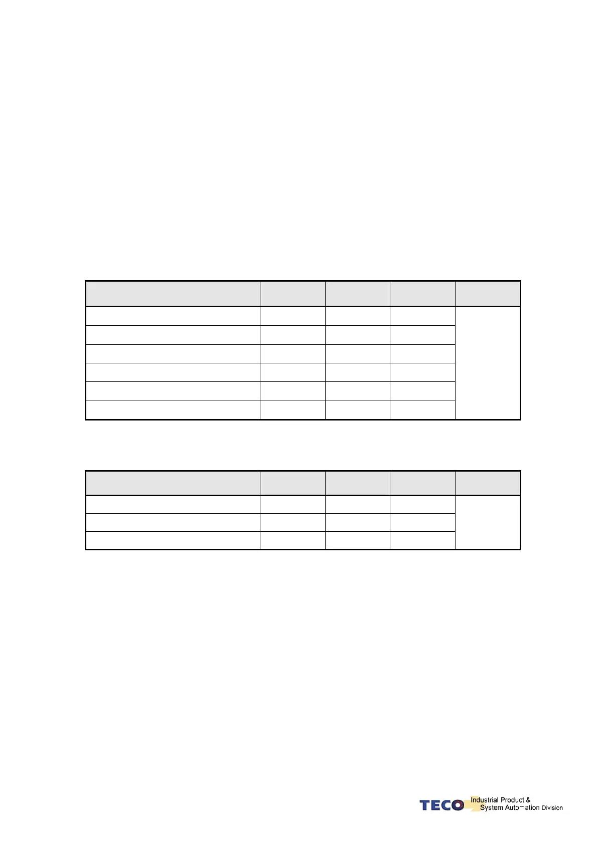
Digital input terminal layout provides 6 (Pin1~13, 14~16) programmable terminal; digital output terminal
provides 4 (Pin18~20) programmable terminals. The diagram below shows the default digital input/output
terminal placement and functions. Please refer to 5-6-1 to check related parameters setting.
Default Digital Input Terminal placement Functions and Wired Mode
Signal
Terminal
Layout
Default
Function
Pin No. Wired Mode
Servo ON DI-1 SON 1
Alarm reset DI-2 ALRS 14
PI/P Switch DI-3 PCNT 2
Servo Lock DI-4 LOK 15
Internal speed command 1 DI-5 SPD1 3
External Torque Limit DI-6 TLMT 16
IO1
Default Digital Input Terminal Layout Functions and Wired Mode
Signal
Terminal
Layout
Default
Function
Pin No. Wired Mode
Servo ready DO-1
RDY
18
Alarm DO-2
ALM
19
Zero speed DO-3
ZS
20
IO1

 Loading...
