2-22
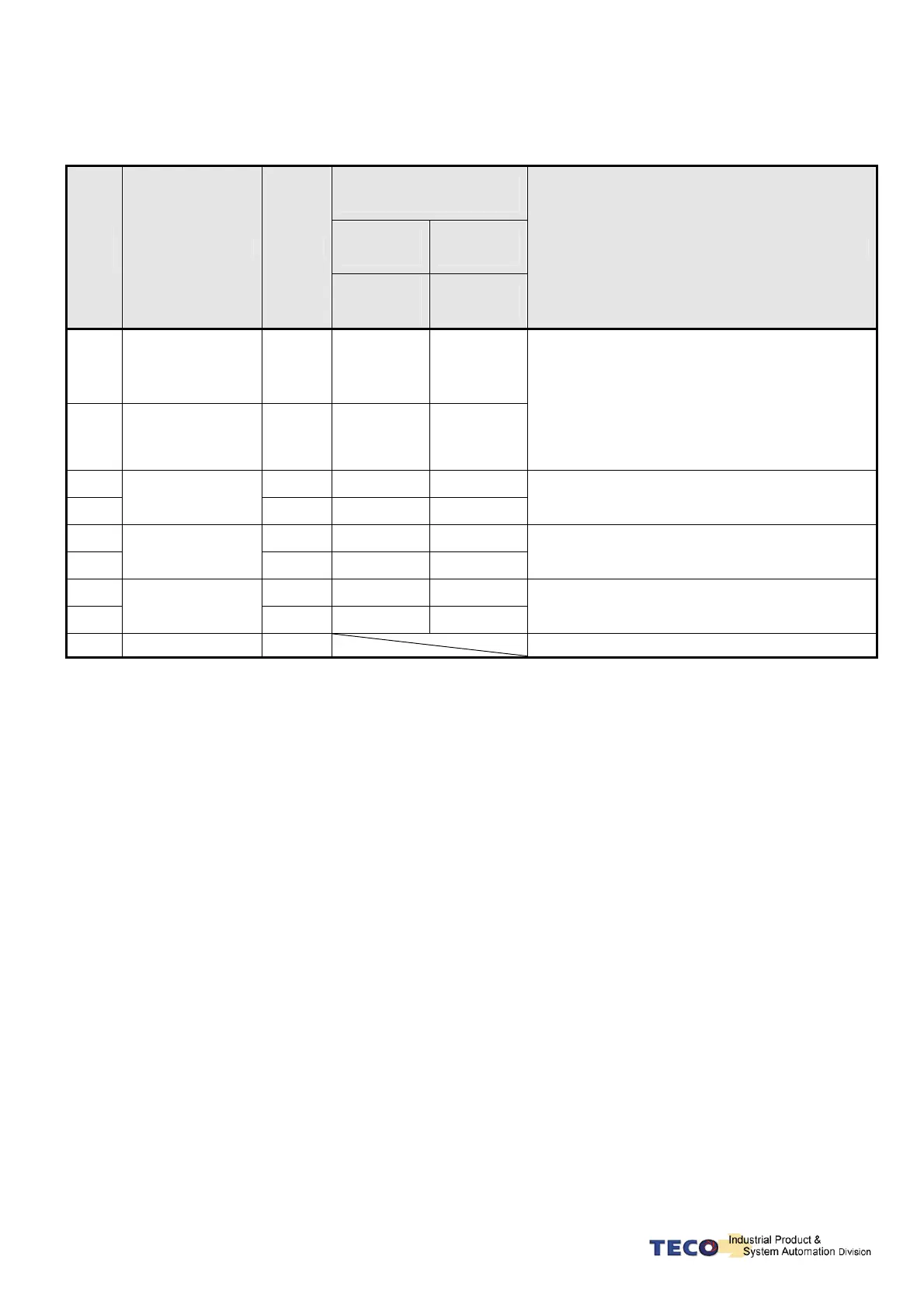
(2) Name and Explanation of I/O Signal:
Encoder Output
No. and Color
General
Joint
Plug-in
Joint
Pin
No.
Signal Name Code
9 wires
(fewer
wiring)
Output
No.
Terminal Layout Function
5
Power output
+ Terminal
+5V
white
B
4
Power output
- Terminal
0V
Black
I
5V Power for encoder (provided from driver).
When the cable is more than 20m, user should
separately use 2 cables to avoid decreasing
voltage of encoder. When the cable is more than
30m, please contact to the distributorship.
3 A
Green
A
2
A Phase encoder
input A
/A
Blue
C
Encoder A Phase: From motor terminal to the
driver.
1 B
Red
H
9
B Phase encoder
input
/B
Pink
D
Encoder B Phase: From motor terminal to the
driver.
8 Z
Yellow
G
7
Z Phase encoder
input
/Z
Orange
E
Encoder Z Phase: From motor terminal to the
driver.
6
No operated
Do not wire.

 Loading...
