3-11
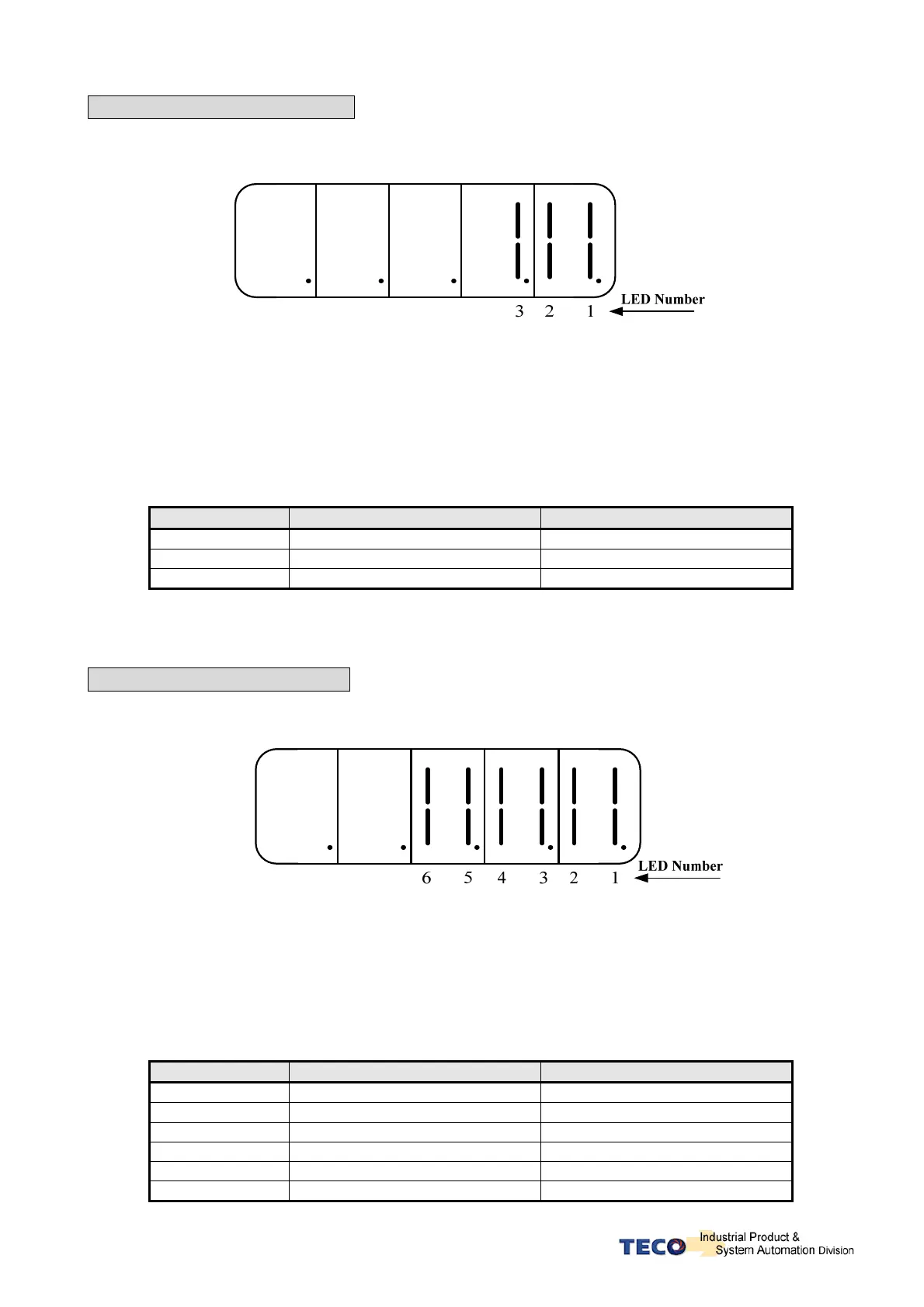
dn-02 (Output terminal status)
z Use dn-02 to check the status of output terminals.
z Output status display is described below:
z When output terminal signal has a low logic level (close loop with IG24), the corresponding LED
will be on.
z When output terminal signal has a high logic level (open loop with IG24), the corresponding LED
will be off.
z Table below shows the functions of the digital outputs.
Default settings are shown below.
For programmable digital output list see section 5-6-1.
LED No. Output terminal number Default function
1 DO-1 RDY
2 DO-2 ALM
3 DO-3 ZS
Note: To set the logic state (High or Low) of for programmable digital outputs refer
to section 5-6-1.
dn-03 (Input terminals status)
z Use dn-03 to check the status of Input terminals.
z Digital Input status display is described below:
z When Input terminal signal has a low logic level (close loop with IG24), the corresponding LED will
be on.
z When Input terminal signal has a high logic level (open loop with IG24), the corresponding LED
will be off.
z Table below shows the functions of the digital input.
Default settings are shown below.
For programmable function list see section 5-6-1.
LED Number Input terminal number Default function
1 DI-1 SON
2 DI -2 ALRS
3 DI -3 PCNT
4 DI -4 LOK
5 DI -5 SPD1
6 DI -6 TLMT
 Loading...

