5-31
z Two types of pulse command can be connected, (Open collector) and (Line driver).
z Please refer to section 2-2-1 for the pulse wiring method.
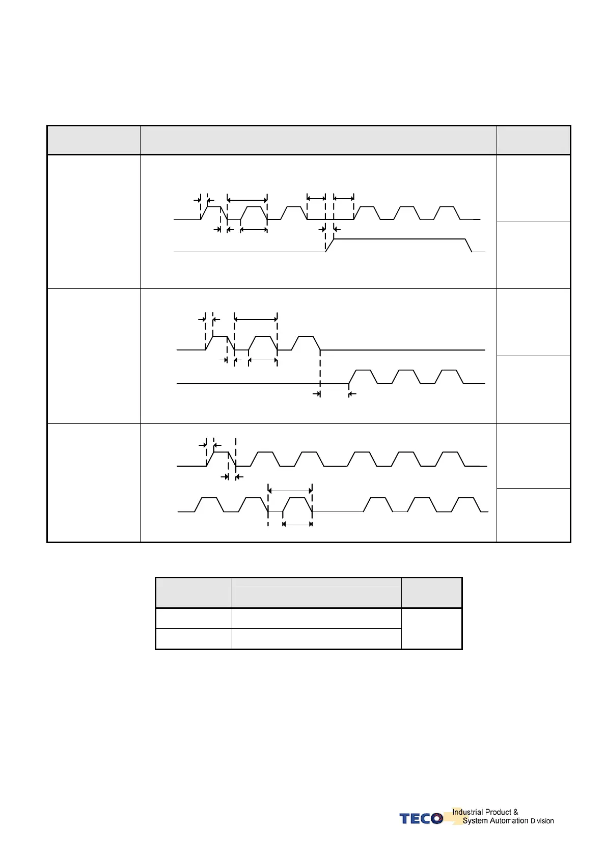
z Pulse command timing should be in accordance with the time sequence standard below.
Pulse Command
Types
Time Sequence Diagram of Pulse Command Time Standard
Line Driver:
t1, t2 ≦ 0.1μs
t3 > 3μs
τ ≧ 1.0μs
(τ/T) ≦ 50%
(Pulse)+
(Sign)
t3 t3
t2
t1
T
t
t2
Pulse
Sign
OpenCollector:
t1, t2 ≦ 0.2μs
t3 > 3μs
τ ≧ 2.0μs
(τ/T) ≦ 50%
LineDrive:
t1, t2 ≦ 0.1μs
t3 > 3μs
τ ≧ 1.0μs
(τ/T) ≦ 50%
(CCW)/
(CW) Pulse
t1
t2
T
t
t3
Pulse
Sign
OpenCollector:
t1, t2 ≦ 0.2μs
t3 > 3μs
τ ≧ 2.0μs
(τ/T) ≦ 50%
LineDrive:
t1, t2 ≦ 0.1μs
τ ≧ 1.0μs
(τ/T) ≦ 50%
AB-Phase Pulse
t2
t1
T
t
Pulse
Sign
OpenCollector:
t1, t2 ≦ 0.2μs
τ ≧ 2.0μs
(τ/T) ≦ 50%
Position command can be disabled (Inhibited) by extrernal input contact INH.
Input Contact
INH
Description
Control
Mode
0 Position Pulse command enabled
1 Position Pulse command disabled
Pe
Note: Input contacts status “1” (ON) and “0” (OFF)
Please check section 5-6-1 to set the required high /Low signal levels (PNP/NPN) selection.

 Loading...
